Garmin AQUAMAP 80 Series Owner'S Manual Download Page 29

Serial Port 1

: Sets the input/output format for port 1 to use 

when connecting the chartplotter to external NMEA devices, 

computers, or other Garmin devices.

Serial Port 2

: Sets the input/output format for port 2 to use 

when connecting the chartplotter to external NMEA devices, 

computers, or other Garmin devices.

NMEA 0183 Setup

: Sets the NMEA 0183 sentences the 

chartplotter transmits, how many digits to the right of the 

decimal point are transmitted in a NMEA output, and how 

waypoints are identified (

NMEA 0183 Settings

, page 23

).

Marine Network

: Allows you to view the devices with which you 

are sharing maps, sonar, or radar. Not available on all 

chartplotter models.

NOTE: 

You can only view networked data on a model that 

supports that data. For example, you cannot view networked 

radar on model that does not support radar.

NMEA 0183

The chartplotters support the NMEA 0183 standard, which is 

used to connect various NMEA 0183 devices, such as VHF 

radios, NMEA instruments, autopilots, wind sensors, and 

heading sensors.
To connect the chartplotter to optional NMEA 0183 devices, see 

the chartplotter installation instructions.
The approved NMEA 0183 sentences for the chartplotter are 

GPAPB, GPBOD, GPBWC, GPGGA, GPGLL, GPGSA, GPGSV, 

GPRMB, GPRMC, GPRTE, GPVTG, GPWPL, GPXTE, and 

Garmin proprietary sentences PGRME, PGRMM, and PGRMZ.
This chartplotter also includes support for the WPL sentence, 

DSC, and sonar NMEA 0183 input with support for the DPT 

(depth) or DBT, MTW (water temperature), and VHW (water 

temperature, speed, and heading) sentences.

NMEA 0183 Settings

Select 

Settings

 > 

Communications

 > 

NMEA 0183 Setup

.

Sounder

: Enables NMEA 0183 output sentences for the 

sounder (if applicable).

Route

: Enables NMEA 0183 output sentences for routes.

System

: Enables NMEA 0183 output sentences for system 

information.

Garmin

: Enables NMEA 0183 output sentences for Garmin 

proprietary sentences.

Posn Precision

: Adjusts the number of digits to the right of the 

decimal point for transmission of NMEA output.

Waypoint IDs

: Sets the device to transmit waypoint names or 

numbers via NMEA 0183 while navigating. Using numbers 

may resolve compatibility issues with older NMEA 0183 

autopilots.

Diagnostics

: Displays NMEA 0183 diagnostic information.

Defaults

: Restores the NMEA 0183 settings to the original 

factory defaults.

Setting Alarms

Navigation Alarms

Select 

Settings

 > 

Alarms

 > 

Navigation

.

Arrival

: Sets an alarm to sound when you are within a specified 

distance or time from a turn or a destination.

Anchor Drag

: Sets an alarm to sound when you exceed a 

specified drift distance while anchored.

Off Course

: Sets an alarm to sound when you are off course by 

a specified distance.

System Alarms

Alarm Clock

: Sets an alarm clock.

Device Voltage

: Sets an alarm to sound when the battery 

reaches a specified low voltage.

GPS Accuracy

: Sets an alarm to sound when the GPS location 

accuracy falls outside the user-defined value.

Units Settings

Select 

Settings

 > 

Units

.

System Units

: Sets the unit format for the device.

Variance

: Sets the magnetic declination, the angle between 

magnetic north and true north, for your present location.

North Reference

: Sets the direction references used in 

calculating heading information. True sets geographic north 

as the north reference. Grid sets grid north as the north 

reference (000º). Magnetic sets the magnetic north as the 

north reference.

Position Format

: Sets the position format in which a given 

location reading appears. Do not change this setting unless 

you are using a map or chart that specifies a different 

position format.

Map Datum

: Sets the coordinate system on which the map is 

structured. Do not change this setting unless you are using a 

map or chart that specifies a different map datum.

Pressure Ref. Time

: Sets the reference time used to calculate 

the barometer trend. The trend is indicated in the barometer 

field.

Time Format

: Sets a 12-hour, 24-hour, or UTC time format.

Time Zone

: Sets the time zone, or allows automatic selection 

based on GPS location.

Navigation Settings

NOTE: 

Some settings and options require additional charts or 

hardware.
Select 

Settings

 > 

Navigation

.

Route Labels

: Sets the type of labels shown with route turns on 

the map.

Auto Guidance

: Sets the measurements for the Safe Depth, 

Safe Height, and Shoreline Distance, when you are using 

some premium maps.

Turn Transition Activ.

: Sets the turn transition to be calculated 

based on time or distance.

Turn Transition Time

: Sets how many minutes before the turn 

that you transition to it as the next leg, when Time is selected 

for the Turn Transition Activ.. You can raise this value to help 

improve the accuracy of the autopilot when navigating a route 

or an Auto Guidance line with many frequent turns or at 

higher speeds. For straighter routes or slower speeds, 

lowering this value can improve autopilot accuracy.

Turn Transition Dist.

: Sets how far before the turn that you 

transition to it as the next leg, when Distance is selected for 

the Turn Transition Activ.. You can raise this value to help 

improve the accuracy of the autopilot when navigating a route 

or an Auto Guidance line with many frequent turns or at 

higher speeds. For straighter routes or slower speeds, 

lowering this value can improve autopilot accuracy.

Route Start

: Selects a starting point for route navigation.

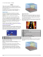
Auto Guidance Line Configurations

 CAUTION

The Safe Depth and Safe Height settings influence how the 

chartplotter calculates an Auto Guidance line. If an area has an 

unknown water depth or an unknown obstacle height, the Auto 

Guidance line is not calculated in that area. If an area at the 

beginning or the end of an Auto Guidance line is shallower than 

the safe water depth or lower than the safe obstacle height, the 

Auto Guidance line is not calculated in that area. On the chart, 

the course through those areas appears as a gray line. When 

your boat enters one of those areas, a warning message 

appears.

Device Configuration

23

Summary of Contents for AQUAMAP 80 Series

Page 1: ...AQUAMAP 80 100 Series Owner s Manual November 2016 Printed in Taiwan 190 01657 00_0C...

Page 2: ...e Garmin logo BlueChart g2 Vision and MapSource are trademarks of Garmin Ltd or its subsidiaries registered in the USA and other countries AQUAMAP GMR GXM and HomePort are trademarks of Garmin Ltd or...

Page 3: ...wing a Direct Course Using Go To 8 Setting and Following a Course Using Auto Guidance 8 Stopping Navigation 8 Waypoints 8 Marking Your Present Location as a Waypoint 8 Creating a Waypoint at a Differe...

Page 4: ...Defining a Circular Guard Zone 18 Defining a Partial Guard Zone 18 Marking a Waypoint on the Radar Screen 18 Showing MARPA Targets in Sentry Mode 18 Radar Targeting and MARPA 18 MARPA Targeting Symbol...

Page 5: ...25 Registering Your Device 25 Cleaning the Screen 25 Screenshots 25 Capturing Screenshots 25 Copying Screenshots to a Computer 25 Troubleshooting 25 Restoring the Original Chartplotter Factory Settin...

Page 6: ......

Page 7: ...use optional memory cards in the chartplotter Map cards allow you to view high resolution satellite imagery and aerial reference photos of ports harbors marinas and other points of interest You can us...

Page 8: ...d the boat according to your course and provides a visual navigation aid This view is helpful when navigating tricky shoals reefs bridges or channels and when trying to identify entry and exit routes...

Page 9: ...line indicates that Auto Guidance cannot calculate part of the Auto Guidance line This is due to the settings for minimum safe water depth and minimum safe obstacle height 6 Follow the magenta line s...

Page 10: ...GPS heading time that has elapsed since the last position of the vessel was reported nearest approach and time to the nearest approach AIS Targeting Symbols Symbol Description AIS vessel The vessel is...

Page 11: ...a time at which the alarm will sound if a target is determined to intersect the safe zone For example to be notified of a pending intersection 10 minutes before it will likely occur set Time To to 10...

Page 12: ...d wind angle from the wind sensor The Manual setting calculates the laylines by using manually entered windward and leeward angles Tide Correction Corrects the laylines based on the tide Navigation an...

Page 13: ...Fish Symbols Shows suspended targets Navigation with a Chartplotter CAUTION If your vessel has an autopilot system a dedicated autopilot control display must be installed at each steering helm in orde...

Page 14: ...center of the magenta line is a thinner purple line that represents the corrected course from your current location to the destination The corrected course is dynamic and it moves with your boat when...

Page 15: ...with premium charts in some areas 1 From the Navigation chart or Fishing chart select a destination 2 Select Navigate To Route To 3 Select the location of the last turn before the destination 4 Select...

Page 16: ...l Saved Routes Select Nav Info Manage Data Clear User Data Routes Tracks A track is a recording of the path of your boat The track currently being recorded is called the active track and it can be sav...

Page 17: ...pe rename a boundary line show or hide a boundary line or edit the turns of a boundary line 1 From the Fishing chart or Navigation chart select MENU Boundary Line Review Edit Boundary 2 Select an opti...

Page 18: ...auge Magnetic heading is the heading data received from a heading sensor and GPS heading is calculated by your chartplotter GPS course over ground 1 Select Gauges Environment MENU Heading Source 2 Sel...

Page 19: ...of the sonar readings from a transducer The range scale along the right side of the screen shows the depth of detected objects as the screen scrolls from the right to the left Depth information Suspe...

Page 20: ...lect Contrast While in another sonar view select Sonar Setup Advanced Color Gain 3 Select an option To increase or decrease the color intensity manually select Up or Down To use the default setting se...

Page 21: ...ation is displayed on screen In deeper water you might want to increase the scroll speed On screen Control Sets what the buttons on the sonar screen control This is available for touchscreen devices R...

Page 22: ...ture Graph Range and Time Scales You can indicate the amount of time and the range of depth that appear in the depth and water temperature graphs 1 Select Sonar Data Graphs MENU 2 Select Depth Graph S...

Page 23: ...essels Individual Routine Calls When you connect the chartplotter to a Garmin VHF radio you can use the chartplotter interface to set up an individual routine call When setting up an individual routin...

Page 24: ...where the radar is being used Especially in inclement weather longer range radar signals can increase the clutter on the Radar screen and make it more difficult to view information about shorter rang...

Page 25: ...n which AIS vessels appear select Display Range and select a distance To show details about AIS activated vessels select Details Show To set the projected heading time for AIS activated vessels select...

Page 26: ...optimized for that mode and may differ from the automatic gain setting used for another mode NOTE Depending upon the radar in use the gain setting configured for use in one radar mode may or may not b...

Page 27: ...Radar Setup Appearance NOTE These settings do not apply to the Radar overlay Color Scheme Sets the color scheme Look Ahead Speed Shifts your present location toward the bottom of the screen automatica...

Page 28: ...transducer If the transducer is installed at the water line measure the distance from the transducer location to the keel of the boat Enter this value in steps 3 and 4 as a positive number If the tra...

Page 29: ...acy falls outside the user defined value Units Settings Select Settings Units System Units Sets the unit format for the device Variance Sets the magnetic declination the angle between magnetic north a...

Page 30: ...whether the line safely avoids known obstacles and the turns enable efficient travel Auto Guidance maintains a wide clearance from obstacles in open water even if you set the Shoreline Distance setti...

Page 31: ...Data to a Chartplotter 1 Insert a memory card into a card reader that is attached to the computer 2 Copy a backup file from the computer to the memory card into a folder named Garmin UserData 3 Inser...

Page 32: ...can purchase complete information about National Marine Electronics Association NMEA format and sentences from NMEA Seven Riggs Avenue Severna Park MD 21146 USA www nmea org Software License Agreement...

Page 33: ...gnals 2 WAAS 21 GPS accuracy 23 H hazard colors 7 help See product support home screen customizing 2 K keel offset 22 keys 1 power 1 shortcut 1 L lane width 7 language 21 M man overboard 8 marine serv...

Page 34: ...recording 11 saving 10 saving as route 10 showing 6 10 transducer 13 15 16 trip gauges 11 12 U unit ID 22 24 25 units of measure 23 updates software 1 user data deleting 11 V vessel trails 6 17 VHF r...

Page 35: ......

Page 36: ...55 69 33 99 39 02 36 699699 52 001 855 792 7671 0800 427 652 0800 0233937 47 815 69 555 00800 4412 454 44 2380 662 915 35 1214 447 460 386 4 27 92 500 0861 GARMIN 427 646 27 0 11 251 9800 34 93 275 44...

Reviews: