Garmin G5 Install Manual & Pilot's Guide
190-02072-00 Rev. E
15
Unit Installation
Installation Manual
Pilot's Guide
Appendix
Index
1.2.2.2.6 Can B
uS
t
rouBLeShootinG
The CAN bus is very simple, and a properly installed CAN bus is very reliable. If
problems are occurring, the following steps can help to identify the issue.
1)
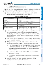
Review the status LED of devices on the CAN bus such as the GSA 28
servos. The status LED indications are listed in Table 1-4.
Table 1-4 Status LED Indications
LED Indication
Description
No Light
No power
Steady Green
On but not communicating via CAN bus
Flashing Green
On and communicating via CAN bus
Red
Hardware fault
Alternating Red/Green
CAN bus network error (two identical LRUs are
configured with the same unit ID)
2)
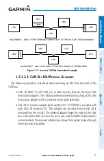
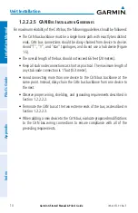
Make sure that the CAN bus is daisy-chained between CAN devices around
the system, and that CAN devices are not connected via a single point
(star topology) or routed through a hub device. This can cause unwanted
signal reflections and “orphan” some devices on the bus and prevent their
communication.
3)
Make sure the CAN bus is terminated in only two locations, and only at the
extreme ends of the CAN bus.
4)
With power removed, remove the CAN bus connector from one of the
devices that is not located at either of the extreme ends of the CAN bus.
a) Using an ohm meter, verify that the resistance between the CAN-H and
CAN-L pins on the connector is 60
Ω
. This will verify that the CAN
backbone is properly terminated at each end (two 120
Ω
terminating
resistors in parallel).
b) A resistance of 120
Ω
indicates that one of the two required CAN
terminations is missing.
c) A resistance of 40
Ω
or less indicates that too many terminations are
installed.
5)
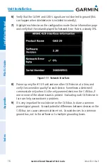
Verify that the CAN-H and CAN-L signals are not swapped, shorted
together, or open-circuited at any LRU connector.
Summary of Contents for Approach G5 - GPS-Enabled Golf Handheld
Page 1: ...G5 Install Manual Pilot s Guide ...
Page 2: ...Blank Page ...
Page 3: ...INSTALLATION MANUAL PILOT S GUIDE APPENDIX INDEX ...
Page 4: ...Blank Page ...
Page 16: ...Garmin G5 Install Manual Pilot s Guide 190 02072 00 Rev E iv Table of Contents Blank Page ...
Page 237: ...Garmin G5 Install Manual Pilot s Guide 190 02072 00 Rev E Blank Page ...

