Garmin G5 Install Manual & Pilot's Guide
190-02072-00 Rev. E
161
Pilot's Guide
Installation Manual
Pilot's Guide
Appendix
Index
2.6.4 TURN RATE INDICATOR
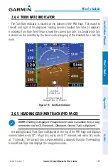
The Turn Rate Indicator is located at the bottom of the PFD Page. Tick marks to
the left and right of the displayed heading denote standard turn rates (3 deg/sec).
A magenta Turn Rate Trend Vector shows the current turn rate. A standard-rate turn
is shown on the indicator by the trend vector stopping at the standard turn rate tick
mark.
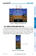
Figure 2-15 Turn Rate Indicator
Turn Rate Indicator
(Standard Rate Tick Marks)
Turn Rate
Trend Vector
2.6.5 HEADING/GROUND TRACK (PFD PAGE)
NOTE:
Heading is displayed if magnetometer data is available from a mag-
netometer via the CAN network. Otherwise, Ground Track is displayed.
A Heading/Ground Track Tape is displayed at the top of the PFD Page and displays
numeric labels every 10°. Major tick marks are at 5° intervals and minor tick marks
at 1° intervals. The current track is represented by a magenta triangle. The Heading/
Ground Track Tape also displays the navigation course.
Summary of Contents for Approach G5 - GPS-Enabled Golf Handheld
Page 1: ...G5 Install Manual Pilot s Guide ...
Page 2: ...Blank Page ...
Page 3: ...INSTALLATION MANUAL PILOT S GUIDE APPENDIX INDEX ...
Page 4: ...Blank Page ...
Page 16: ...Garmin G5 Install Manual Pilot s Guide 190 02072 00 Rev E iv Table of Contents Blank Page ...
Page 237: ...Garmin G5 Install Manual Pilot s Guide 190 02072 00 Rev E Blank Page ...

