background image

Garmin aera 500 Series Pilot’s Guide

190-01117-02  Rev. A

appendix d

138

Overview

GPS Navigation

Flight Planning

Hazar

Avoidance

Additional F

eatur

es

Appendices

Index

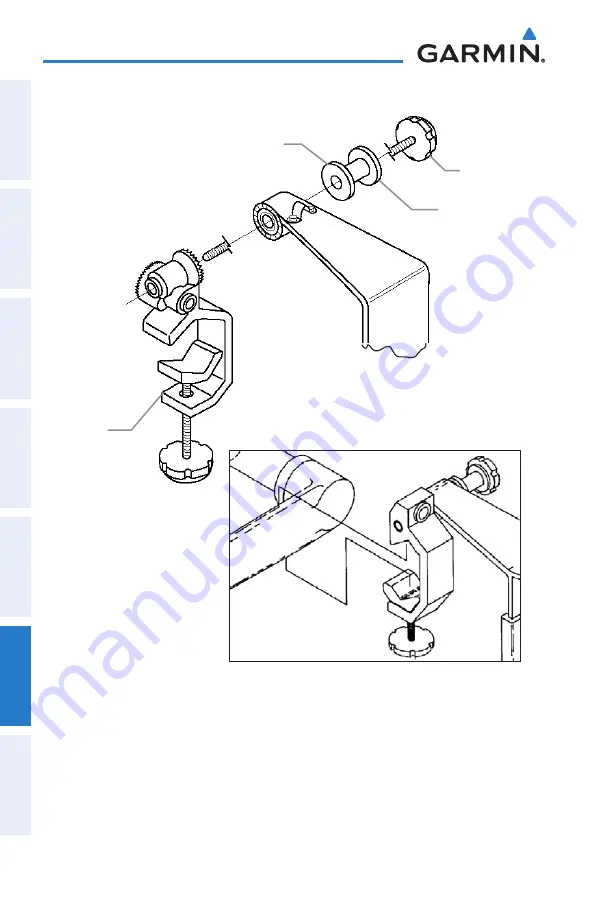
Yoke mount in Conventional Configuration

Yoke mount in Forward-Facing Configuration

Rubber Washer

Cradle 

Adjustment 

Knob

Spacer

Clamp 

Assembly

Securing the cable on the top of the yoke mount:

1) 

Remove the screws securing the cable clamp.

2) 

Orient the cable and secure the clamp with the screws.

Summary of Contents for aera 190-01117-02

Page 1: ...models 500 510 550 560 Pilot s Guide ...

Page 2: ......

Page 3: ...Overview GPS Navigation Flight Planning Hazard Avoidance Additional Features Appendices Index ...

Page 4: ......

Page 5: ...his manual may be reproduced copied transmitted disseminated downloaded or stored in any storage medium for any purpose without the express written permission of Garmin Garmin hereby grants permission to download a single copy of this manual and of any revision to this manual onto a hard drive or other electronic storage medium to be viewed for personal use provided that such electronic or printed...

Page 6: ...G The displayed minimum safe altitudes MSAs are only advisory in nature and should not be relied upon as the sole source of obstacle and terrain avoidance information Always refer to current aeronautical charts for appropriate minimum clearance altitudes WARNING The altitude calculated by aera GPS receivers is geometric height above Mean Sea Level and could vary significantly from the altitude dis...

Page 7: ...ever the pilot must recognize that providing monitoring and or self test capability for all conceivable system failures is not practical Although unlikely it may be possible for erroneous operation to occur without a fault indication shown by the aera It is thus the responsibility of the pilot to detect such an occurrence by means of cross checking with all redundant or correlated information avai...

Page 8: ...plays are subject to change and may not reflect the most current aera system and aviation databases Depictions of equipment may differ slightly from the actual equipment NOTE This product its packaging and its components contain chemicals known to the State of California to cause cancer birth defects or reproductive harm This notice is being provided in accordance with California s Proposition 65 ...

Page 9: ...rolling 14 1 4 Accessing System Functionality 15 Option Menus 15 Data Entry 15 Waypoint Information Tabs 17 1 5 Using Map Displays 17 Map Range 18 Map Panning 19 Map Overlays 21 Map Symbols 22 1 6 System Settings 23 Display 23 Sound 24 Additional Settings 26 1 7 Nearest Airport Criteria Settings 27 1 8 Present Position 28 Position 28 New Location 29 Simulator Mode 29 Section 2 GPS Navigation 31 2 ...

Page 10: ...g Flight Plan 70 3 3 Flight Plan Storage 71 3 4 Flight Plan Activation 72 Editing Speed and Fuel Flow 72 Copying Flight Plans 73 Deleting Flight Plans 73 Inverting a Flight Plan 74 3 5 Approaches 75 Selecting an Approach 76 Activating Vectors to Final 78 Section 4 Hazard Avoidance 79 4 1 XM Weather aera 510 560 79 Activating Services 79 XM Satellite Weather Products 80 Using XM Satellite Weather P...

Page 11: ...th Loss of GPS Position 125 Appendix C Managing Files and Databases 127 Connecting to a Computer 127 Managing Files 128 MicroSD Card Use Optional 130 Databases 131 Appendix D Installation and Interfacing 135 Mounting the aera in the Aircraft 135 Connecting to a Garmin VHF Comm Radio 139 Information about USB Drivers 141 Connecting the GXM 40 Antenna aera 510 560 141 Connecting to a GTX 330 Mode S ...

Page 12: ...dix H Display Symbols 167 VFR Symbols 167 IFR Symbols 168 Airspace Symbols 170 Appendix I Map Datum and Location Formats 173 Map Datums 173 Location Formats 173 Appendix J Glossary 175 Appendix K License Agreement and Warranty 181 Contact Garmin 181 Software License Agreement 181 Limited Warranty 181 AOPA Airport Directory Notice 182 XM Satellite Radio Service Agreement 182 Weather Data Warranty 1...

Page 13: ... derived analog flight instrumentation position navigation and hazard avoidance information to the pilot using a 4 3 QWVGA color display with Touch Screen Unit Overview Headphone audio out Jack Under Weather Cap External Antenna Connec tor Under Weather Cap Power Button Microphone Release Key Slide and Release to Open the Battery Cover Serial Number Under the Battery Speaker GPS Antenna Mini USB C...

Page 14: ...the unit from the aircraft or vehicle when exiting or store it out of direct sunlight Installing the battery 1 Locate the lithium ion battery that came in the product box 2 Slide the release key until the battery cover on the back of the aera opens up 3 Remove the battery cover 4 Locate the metal contacts on the end of the lithium ion battery 5 Insert the battery so that the metal contacts on the ...

Page 15: ... aera in the aircraft refer to Appendix D Installation and Interfacing and connect the power cable to the aircraft power outlet cigarette lighter receptacle 2 Route the power cable so that it does not interfere with aircraft operation The unit begins charging as soon as external power is applied Using charge mode Applying external power to the aera automatically turns on the unit for full operatio...

Page 16: ...n the world Duringinitialization currentdatabaseinformationisdisplayed Databaseinformation includes valid operating dates cycle number and database type When this information has been reviewed for currency to ensure that no databases have expired the pilot is prompted to continue Touching the Press To Accept Button acknowledges this information and the Home Screen is displayed Database Initializat...

Page 17: ... a fix 2D GPS Location At least three satellites have been acquired and a two dimensional location fix has been calculated 2D Differential appears when you are receiving DGPS corrections in 2D mode 3D GPS Location At least four satellites have been acquired and a three dimensional fix has been calculated 3D Differential appears when you are receiving DGPS corrections in 3D mode Lost Satellite Rece...

Page 18: ...n at their respective positions on a satellite constellation diagram The outer circle of the constellation diagram represents the horizon the inner circle represents 45 above the horizon and the center point shows the position directly overhead Each satellite is represented by a square containing the Pseudo Random Noise PRN number i e satellite identification number GPS Status can be helpful in tr...

Page 19: ... to the Home screen Back Displays the previous page Returns Home touch and hold OK Commits a value edited or selected Menu Displays the context sensitive option menu Menu Displays the menu Displays the Direct to function touch and hold Up Scrolls up Down Scrolls down Direct to Displays the Direct to function Out Zooms out In Zooms in KeyPad Controls OK Exits the keypad function and accepts the cha...

Page 20: ...unction Map Displays the Navigation Map Terrain Displays the Terrain Map HSI Panel Displays the Panel Mode Nearest Displays the second level Nearest Icons Numbers Displays flight data Active FPL Displays the Active Flight Plan WPT Info Displays the Waypoint Information Direct To Displays the Direct To function Position Displays the aircraft s Present Position Weather Displays second level Weather ...

Page 21: ...he following icons to perform the associated function Airport Displays nearest airports Airport WX Displays nearest airport weather VOR Displays nearest VORs NDB Displays nearest NDBs Intersection Displays nearest intersections VRP Displays nearest Visual Reporting Point VRP Atlantic User WPT Displays nearest user waypoints City Displays nearest cities ARTCC Displays nearest ARTCCs FSS Displays ne...

Page 22: ...e Screen touch the Weather Icon to access the second level Weather Icons Touch the following second level Weather Icons to display the weather product on the Weather Map NEXRAD Displays NEXRAD NEXt generation RADar Satellite Displays Satellite Mosaic cloud cover Echo Tops Displays Echo Tops Winds Displays Winds Aloft Lightning Displays Lightning Storm Cells Displays Storm Cells METAR Displays META...

Page 23: ...ETs TFR Displays TFRs Temporary Flight Restrictions PIREP Displays PIREPs Freeze Lvl Displays Freezing Levels Turb Fcst Displays the Turbulence Forecast Icing Fcst Displays the Icing Forecast WX Frst Displays Forecast Information current 12 24 36 48 Pressure Displays Surface Pressure Sea Temp Displays Water Temperature Tools From the Home Screen touch the Tools Icon to access the second level Tool...

Page 24: ...evel Setup Icons User WPT Displays User Waypoints and Proximity Waypoints Flight Log Displays Flight Logs Track Log Displays Track Logs FPL List Displays the Flight Plan List VNAV Displays Vertical Navigation Profile Displays Aircraft Profiles E6B Calc Displays the E6B Calculator Weight Bal Displays the Weight Balance Database Displays database and software version information Automotive Activates...

Page 25: ... the following third level icons to perform the associated function Display Displays backlight intensity timeout and color mode settings Sound Displays sound settings Units Displays unit settings Date Time Displays date time settings Map Displays Navigation Map settings Position Displays position settings Interface Displays interface settings Alarms Displays alarm settings SUA Alarms Displays Spec...

Page 26: ...ndices Index Selecting a Function Selecting a function Touch the desired icon The icon will momentarily turn blue when selected Terrain Icon Selected Home Screen Scrolling Scrolling up down on the touchscreen Touch the Up or Down Arrow Icons if available Or If the arrow icons are present touch and drag your finger up or down Scrolling Weather Icons ...

Page 27: ...n Data Entry Alphanumeric data can be entered using the keypad In some instances such as when entering an identifier the aera tries to predict the desired identifier based on the characters being entered In this case if the desired identifier appears use the OK Icon to confirm the entry without entering the rest of the identifier manually This can save the pilot from having to enter all the charac...

Page 28: ... button Touch the keypad to enter the desired data Touch OK Numeric data may also be entered using or buttons if applicable Entering predetermined data options Touch the Data Option Button to display a vertical list of data options if applicable or to toggle two data options i e On Off Or Touch the buttons to cycle through a horizontal list if more than two data options are available If using the ...

Page 29: ...Freq Runway WX optional AOPA optional 1 5 Using Map Displays NOTE Refer to the GPS Navigation section for more information on Map Display Setup Map displays are used extensively in the aera to provide situational awareness in flight Most aera maps can display the following information Airports NAVAIDs airspaces airways land data highways cities lakes rivers borders etc with names Map Pointer infor...

Page 30: ...g or zoom in decreasing Adjusting the map range While viewing a Map Display touch the In or Out Icons Navigation Map Map Range Range Icons When the selected range exceeds the resolution of the map data overzoom appears below the map range scale Map Range Overzoom Scale Bar Rep resenting a Map Scale of 3 nm Per Scale Width Auto Zoom Auto Zoom allows the aera to change the map display range to the s...

Page 31: ...selected by touching anywhere on the Map the Map Pointer is displayed An Information Window also appears at the bottom of the map display showing the the bearing distance and time to the pointer from the aircraft s present position the elevation of the land at the position of the pointer or the object s airports obstacles etc elevation if known When the Map Pointer is over a map feature the map fe...

Page 32: ...ch anywhere on the map and drag Touch the Cancel icon to remove the map pointer Reviewing information for a map feature While viewing a Map Display touch anywhere on the map to activate the map pointer When the Map Pointer is over a map feature the map feature is highlighted an information box appears on the map and the highlighted map feature is displayed on the Map Feature Button at the bottom o...

Page 33: ...e Weather Topography Terrain and Satellite Imagery map overlays can be displayed or removed Displaying removing map overlays 1 From the Home Screen touch Map Menu Show Hide 2 Touch the Show Hide Data Option Button for the desired overlay Satellite View only displays satellite imagery at and above the 20nm range Below the 20nm range no sat view is displayed below the map range ...

Page 34: ... Home Screen touch Map Menu Declutter 2 Touch the desired level 1 2 3 on the right side of the screen The currently selected level is highlighted blue 3 Touch the Back Icon to remove the detail options Declutter Map Detail The map detail can also be adjusted Map detail changes the amount of detail with respect to the zoom scale Adjusting the map detail 1 From the Home Screen touch Map Menu Set Up ...

Page 35: ...ement of the following system parameters Display Sound Units Date Time Map Position Interface Alarms SUA Alarms Power Restoring system setting defaults 1 From the Home Screen touch Tools Setup 2 Touch the desired Setup Icon Display Sound Units Date Time Map Position Interface Alarms SUA Alarms or Power 3 Touch Menu Restore Default Or From the Home Screen touch Tools Setup Menu Restore All Settings...

Page 36: ... Adjusting backlight timeout 1 From the Home Screen touch Tools Setup Display 2 Touch the Backlight Timeout Data Option Button and touch the desired option from the list Stays On 15 Seconds 30 Seconds 1 Minute or 2 Minutes Touchscreen Calibrating the touchscreen 1 From the Home Screen touch Tools Setup Display Menu Calibrate 2 Follow the onscreen instructions and touch OK The unit will restart Sou...

Page 37: ...ols Setup Sound 2 Touch the buttons to adjust the sound Or Touch the Icon to mute the Master Alerts or Media audio A blue X will appear over the icon Or Touch the On Off Data Option Button to toggle Terrain Audio TIS Audio or Key Tones on or off Or 1 Press the POWER Button to quickly access the Master volume mute 2 Touch Menu Sound Setup to access ALL volume settings Muting sound See the Adjusting...

Page 38: ...s displayed with a blue outline around the current setting Touch the or buttons to increase decrease the numerical values if necessary 4 Touch and hold the Back Icon to return to the Home Screen Icon Available Settings Display Backlight Intensity Backlight Timeout Color Mode Screenshot Calibration from Option Menu Sound Master 0 10 Alerts 0 10 Media 0 10 Key Tone Terrain Audio TIS Audio Units Dist...

Page 39: ...ays with a concrete asphalt or similar sealed surface Hard or Soft shows all runways except water landing facilities Water Only shows only water landing facilities Any shows any runway regardless of surface type including water landing facilities Minimum Runway Length allows the pilot to enter a specific length for the shortest runway allowed Entering airport criteria 1 From the Home Screen touch ...

Page 40: ... to display the current position in relation to a prominent landmark The pilot can change the reference waypoint Nearest Type using the Change Nearest Type menu option By default the Nearest Type is set to Automatic which will display the nearest large airport enroute VOR or city in that order Present Position Changing the Nearest Type 1 From the Home Screen touch Position Menu Change Nearest Type...

Page 41: ...with the unit indoors or when no satellite or XM signals are available All waypoints and routes created in Simulator Mode are retained in memory for future use NOTE Do not attempt to navigate using Simulator Mode When the unit is set to Simulator Mode the GPS receiver is turned off Any Satellite Signal Strength Bars shown are only simulations and do not represent the strength of actual satellite s...

Page 42: ...Garmin aera 500 Series Pilot s Guide 190 01117 02 Rev A 30 Overview Overview GPS Navigation Flight Planning Hazard Avoidance Additional Features Appendices Index Simulator Mode ...

Page 43: ...s North Up NORTH UP Track Up TRK UP or Desired Track Up DTK UP An aircraft icon is placed on the Navigation Map at the location corresponding to the calculated present position The aircraft position and the flight plan legs are accurately based on GPS calculations The basemap upon which these are placed are from a source with less resolution therefore the relative position of the aircraft to map f...

Page 44: ...dex Data Fields The data fields on the Navigation Map can be independently configured by the user Data Fields Navigation Map Data Fields By default the Data Bar Fields are set to display Ground Speed GS Distance Next DIST NEXT Vertical Speed Required VSR and Time En Route Next ETE NEXT These four data fields can be changed to display any of the Data Field Options ...

Page 45: ...Additional Features Appendices Index Changing the information shown in the data fields From the Home Screen touch the Map Icon Touch the Menu Icon Touch the Change Data Fields menu option Touch the desired Data Field to change A list of available Data Field Options is displayed Touch the desired Data Field Option Touch the OK Icon ...

Page 46: ...Safe Altitude ESA External Voltage EXT VOLTS Flight Timer FLT TIMER Fuel Timer Glide Ratio G R Ground Speed GS Ground Track TRK Minimum Safe Altitude MSA Next Waypoint NEXT WPT Sunrise Sunset Time En Route Destination ETE DEST Time En Route Next ETE NEXT Time of Arrival Destination ETA DEST Time of Arrival NEXT ETA NEXT Time to VNAV VNAV TIME Time Local Time UTC Vertical Speed VS Vertical Speed Re...

Page 47: ...n be independently configured by the user Accessing numeric flight data From the Home Screen touch Numbers Changing numeric flight data fields 1 From the Home Screen touch Numbers 2 Touch the desired data field to change The available data fields are displayed 3 Touch the desired data field 4 Touch OK Restoring default numeric flight data From the Home Screen touch Numbers Menu Restore Default Num...

Page 48: ...ult Course to Steer a specific heading reference User Selected or Off Compass Arc Navigation Map Compass Arc Magenta Bug Indicator Displaying Removing the Compass Arc from the Navigation Map 1 From the Home Screen touch Map Menu Set Up Map 2 Touch the buttons to select the General Category if necessary 3 Touch Compass Arc 4 Touch the On Off Button Setting the Compass Arc Bug Indicator 1 From the H...

Page 49: ...CDI Scale Adjustment Option Menu The Panel shows a graphic Horizontal Situation Indicator HSI surrounded by additional indicators The graphic HSI depicts the course to the destination or the next waypoint in a flight plan current ground track off course error and a To From indication The rotating compass indicates your current ground track The course pointer and course deviation needle indicate th...

Page 50: ...limits CDI scale 1 25 within 30 nm of any airport in the active route CDI scale 0 25 on an approach leg or within 2 nm of the FAF or MAP CDI scale 5 0 if the previous two conditions do not exist Displaying the HSI Panel From the Home Screen touch the HSI Panel Icon Changing the CDI Scale The CDI scale can be set by touching the In or Out Icons from the HSI Panel Screen if the CDI scale is NOT set ...

Page 51: ...el or the Active FPL Icon 2 Touch the Menu Icon 3 Touch the Set OBS and Hold menu option only available when navigating a Direct To or Flight Plan 4 Touch the or Buttons to increase decrease the value Or Touch the Radial Button to enter the desired radial using the keypad and touch the OK Icon HSI Panel Option Menu Radial Button Set OBS Returning to automatic sequencing of route waypoints 1 From t...

Page 52: ... and the ground speed is greater than 35 knots The Approaching VNAV Profile message appears one minute prior to the initial descent point The descent angle locks to prevent changes in speed from altering the profile TheVNAV feature does not take into account any changes in groundspeed that occur during the transition from level flight to descent or climb At 500 ft above the target altitude the App...

Page 53: ...l center of the HSI the aircraft is at the proper altitude for the VNAV Profile Enabling disabling the VNAV indicator 1 From the Home Screen touch the HSI Panel Icon 2 Touch the Menu Icon 3 Touch the Enable VNAV Indicator or Disable VNAV Indicator menu option only available when navigating a Direct To or Flight Plan Capturing cancelling VNAV profile 1 Enter a valid VNAV profile see Configuring a V...

Page 54: ... Waypoint Enter any waypoint along the currently active route as the reference waypoint The reference waypoint defines the target location Profile Enter the descent rate Altitude Enter the desired reference waypoint altitude Select Above Waypoint to use field elevation for airports in the Jeppesen database or MSL to specify an exact MSL altitude target By Enter the target location with settings of...

Page 55: ...nter location of pointer name and other pertinent information Map range Aircraft icon representing present position Flight plan legs User waypoints Track vector Topography data Map Orientation Maps are shown in one of three different orientation options allowing flexibility in determining aircraft position relative to other items on the map North Up or for determining where map items are relative ...

Page 56: ...ientation 1 From the Home Screen touch Map Menu Set Up Map 2 Touch the buttons to select the General Category if necessary 3 Touch Orientation 4 Touch the buttons to select North Up Track Up or DTK Up Airports Navaids Cities Roads Setting up and customizing airports NAVAIDs cities roads for the navigation map 1 From the Home Screen touch Map Menu Set Up Map 2 Touch the buttons to select the Airpor...

Page 57: ...y serve airliners jets turboprops and turbocharged piston aircraft operating above 18 000 feet MSL Jet Routes start at 18 000 feet MSL and extend upward to 45 000 feet MSL altitudes above 18 000 feet are called flight levels and are described as FL450 for 45 000 feet MSL Jet Routes are designated with a J before the route number Low Altitude Airways are drawn in gray High Altitude Airways are draw...

Page 58: ...d the aera s Spell N Find feature scrolls through the database displaying those waypoints matching the characters which have been entered up to that point A direct to navigation leg to the selected waypoint can be initiated by pressing the Menu Icon The waypoint function allows the pilot to review airport information runway information frequencies AOPA information if available and weather informat...

Page 59: ...Tab if necessary 2 Touch the Waypoint Identifier Button 3 Enter the desired waypoint a Touch the buttons to Search by Identifier Search by Facility Name or Search by City using the keypad b Enter the desired waypoint c Touch the OK Icon Or a Touch the buttons to cycle through the waypoint categories Flight Plan Waypoints Nearest Airports or Recent Waypoints b Touch the desired waypoint from the li...

Page 60: ...tered facility name or location duplicate waypoints are displayed Touch the desired waypoint from the list 5 If multiple runways exist touch the Runway Button and touch the desired runway from the vertical list Or Touch the buttons to cycle through the runways Runway Tab Option Menu Waypoint Information Runway Tab Runway Button Waypoint Identifier Button Length Width Surface Lighting Traffic Patte...

Page 61: ...tion which gives the pilot quick access to nearest airport weather VOR NDB intersection user waypoint city ARTCC FSS and airspace information If there are none available None Within 200 NM is displayed The Nearest functions contain the following information Airport identifier bearing distance length of the longest runway and common traffic advisory CTAF or tower frequency Airport WX Airport Weathe...

Page 62: ...ng nearest information 1 From the Home Screen touch the Nearest Icon to display the second level Nearest Icons 2 Touch the desired Nearest Icon Airport Airport WX VOR NDB Intersection User WPT City ARTCC FSS or Airspace 3 Touch the desired nearest option from the list for additional information Or If viewing Nearest ARTCCs or FSSs touch the buttons to cycle through the list 4 If desired touch Menu...

Page 63: ...ed The NearestAirports Option Menu also allows the pilot to choose between displaying the facility names city names bearing or direction arrows Setting nearest airport criteria Refer to Section 1 4 Airport Criteria Settings Weather Information Textual weather information can be viewed several different ways Viewing airport weather information 1 From the Home Screen touch the WPT Info Icon 2 Enter ...

Page 64: ... menu option 3 Touch the Map Feature Button with the desired identifier displayed refer to Map Panning in the Overview Section for more information The weather information is displayed METAR Selected Weather Information Map Feature Button Accessing Additional information In addition to airport and weather information additional information for VORs NDBs Intersections User Waypoints Cities ARTCCs F...

Page 65: ...tional Features Appendices Index Additional Information Airport VOR NDB Intersection User Wpt City ARTCC FSS Airspace Identifier Frequency Name City State Type Morse Code Radial Region Bearing Distance Lat Long Elevation MSL Fuel Available Time Zone UTC Offset Runway Information AOPA Weather Controlling Agency Vertical Boundaries Class ...

Page 66: ...entifier Field to begin entering the desired intersection Refer to the Overview Section on Data Entry for more information Or 1 From the Home Screen touch Nearest Intersection 2 Touch the desired Nearest Intersection from the list 3 If desired touch Menu Show Map Or 1 From the Home Screen touch the Map Icon 2 Touch the desired Intersection on the map 3 Touch the Map Feature Button with the desired...

Page 67: ...yed refer to the Overview Section on Map Panning for more information The NDB information is displayed VORs VOR information can be viewed using the Waypoint Information function the Nearest function or the Map Panning function The Nearest VOR function can be used to quickly find a VOR close to the flight path The list only includesVORs that are within 200nm If there are noVORs in the list text ind...

Page 68: ...utton with the desired VOR displayed refer to the Overview Section on Map Panning for more information The VOR information is displayed User Waypoints The aera can create and store up to 3 000 user defined waypoints Once a waypoint has been created it can be renamed deleted or moved User Waypoints Creating user waypoints 1 To create a new user waypoint at the current location or using the Map Poin...

Page 69: ...n 3 Touch the OK Icon If changing the User Waypoint settings symbol altitude location or reference waypoints continue with Step 4 4 If desired touch the Symbol Field to change the symbol that will appear on the map a Touch the desired symbol b Touch the OK Icon User Waypoint Symbols 5 If desired touch the Altitude Field a Enter the desired altitude using the keypad or the buttons Refer to the Over...

Page 70: ...nter the desired waypoint b Touch the Bearing and or Distance Fields to enter the desired values c Touch the OK Icon 8 Touch and hold the Back Icon to return to the Home Screen Reference Waypoints Selecting and viewing nearest user waypoints 1 From the Home Screen touch Nearest User WPT 2 Touch the desired User Waypoint The User Waypoint information is displayed 3 If desired touch the Menu Icon an...

Page 71: ...red altitude Refer to the Overview Section on Data Entry for more information Or a Touch the Location Button b Enter the desired latitude and longitude by touching the left right arrows to move the cursor and the up down arrows to change the value 5 Touch the OK Icon Deleting user waypoints 1 From the Home Screen touch Tools User WPT 2 Delete a single waypoint delete all waypoints delete by symbol...

Page 72: ... icon The confirmation window will appear 3 Touch Yes Cities City information can be viewed using theWaypoint Information function the Nearest function or the Map Panning function The Nearest City function can be used to quickly find a city close to the flight path The list only includes cities that are within 200nm If there are no cities in the list text indicating that there are no nearest citie...

Page 73: ...ouch the buttons to cycle through the list The associated bearing distance and frequencies are displayed FSS FSS information can be viewed using the Nearest function The Nearest FSS function can be used to quickly find a FSS close to the flight path The list only includes FSS that are within 200nm If there are no FSSs in the list text indicating that there are no nearest FSSs is displayed FSS freq...

Page 74: ...quencies associated with that airspace Nearest Airspace Airspace Alert Messages If airspace alarms are set to On default is Off the aera will display a message which includes the airspace name time to entry if applicable and status Touch the message to acknowledge it There are four types of status information Ahead Projected to enter the airspace within the next 10 minutes or less Near Within two ...

Page 75: ...Smart Airspace SmartAirspace shows airspace at and immediately surrounding the aircraft s current altitude in bold Airspaces at all other altitudes are de emphasized Smart Airspace De emphasized Airspace Bold Airspace Smart Airspace setup 1 From the Home Screen touch Map Menu Set Up Map 2 Touch the buttons to select the Airspace Category 3 Touch the Smart Airspace 4 Touch the On Off Button ...

Page 76: ... to is activated the aera establishes a point to point course line from the present position to the selected direct to destination Course guidance is provided until the direct to is replaced with a new direct to or flight plan or cancelled Direct To Entering a waypoint identifier facility name or city as a direct to destination 1 From the Home Screen touch the Direct To Icon Or Touch and hold the ...

Page 77: ...ation 1 From the Home Screen touch Nearest Airport 2 Touch the desired nearest airport 3 Touch and hold the Menu Icon 4 Touch the Activate Icon Direct To Shortcut Selecting a waypoint as a direct to destination using the pointer 1 With a map displayed activate the map pointer by touching the desired waypoint If no airport NAVAID or User Waypoint exists at the desired location a temporary waypoint ...

Page 78: ... A 66 GPS Navigation Overview GPS Navigation Flight Planning Hazard Avoidance Additional Features Appendices Index From the Home Screen touch the Active FPL Icon Or Touch and hold the Menu Icon when available 2 Touch the Menu Icon 3 Touch Stop Navigation ...

Page 79: ...m the current database to define the waypoints If the database is changed or updated the aera automatically updates the information if the procedure has not been modified If an approach is no longer available the procedure is deleted from the affected stored flight plan s and an alert is displayed Whenever an approach is loaded into the active flight plan it replaces the destination airport with a...

Page 80: ...he currently selected Data Field is outlined blue 4 Touch the OK Icon 5 If desired repeat Steps 2 4 for the remaining Data Field Data Field Button Flight Plan Data Fields 3 2 Flight Plan Creation The active flight plan is the flight plan to which the aera is currently providing guidance and is shown on the navigation maps Stored flight plans are flight plans available for activation becomes the ac...

Page 81: ...s exist for the entered facility name or location duplicate waypoints are displayed Touch the desired waypoint from the list 5 Repeat Steps 2 5 to enter each additional waypoint Creating a stored flight plan 1 From the Home Screen touch Tools FPL List Menu New Flight Plan 2 Touch the Touch to add Waypoint Button 3 Enter the desired waypoint a Touch the buttons to Search by Identifier Search by Fac...

Page 82: ...ouch the buttons to Search by Identifier Search by Facility Name or Search by City using the keypad b Enter the desired waypoint c Touch the OK Icon Or a Touch the buttons to cycle through the waypoint categories Flight Plan Waypoints Nearest Airports or Recent Waypoints b Touch the desired waypoint from the list 4 If duplicate entries exist for the entered facility name or location duplicate wayp...

Page 83: ...t plan can be viewed using the Flight Plan List function Viewing information about a stored flight plan 1 From the Home Screen touch Tools FPL List 2 Touch the desired saved flight plan An option menu is displayed 3 Touch the Review Flight Plan menu option Flight Plan List Storing an active flight plan 1 With the Active Flight Plan displayed touch the Menu Icon 2 Touch the Save Flight Plan menu op...

Page 84: ...tion menu is displayed 3 Touch the Activate Flight Plan menu option A confirmation window appears 4 Touch Yes Activating a Flight Plan Leg 1 From the Home Screen touch the Active FPL Icon 2 While navigating an active flight plan touch the desired leg to be activated An option menu automatically appears 3 Touch the Activate Leg menu option 4 Touch Yes 3 5 Flight Plan Editing Editing Speed and Fuel ...

Page 85: ... of the original stored flight plan Copying a stored flight plan With the desired Stored Flight Plan displayed touch the Menu Copy Flight Plan Yes Or With the Flight Plan List displayed touch the desired flight plan to copy and touch Copy Flight Plan Deleting Flight Plans Individual or all stored flight plans can be deleted from the aera memory Deleting a stored flight plan With the desired Stored...

Page 86: ...ypoint to be deleted An option menu appears 3 Touch the Remove Waypoint menu option A confirmation window appears 4 Touch Yes Deleting an individual waypoint from a saved flight plan 1 From the Home Screen touch Tools FPL List 2 Touch the desired saved flight plan An option menu is displayed 3 Touch the Review Flight Plan menu option 4 Touch the desired waypoint to be deleted An option menu appear...

Page 87: ...ch fix FAF to missed approach point MAP of the published approach is available for monitoring An approach can be loaded at any airport that has one available and provides guidance for non precision and precision approaches to airports with published instrument approach procedures Only one approach can be loaded at a time in a flight plan If an approach is loaded when another approach is already in...

Page 88: ...plan 1 From the Home Screen touch the Active FPL Icon Or a From the Home Screen touch the Tools Icon b Touch the FPL List Icon c Touch the desired Saved Flight Plan from the list An option menu appears d Touch the Review Flight Plan menu option 2 With the flight plan displayed touch the Menu Icon 3 Touch the Select Approach menu option only available if the destination airport has a published appr...

Page 89: ...t plan and immediately begins to provide guidance to the first waypoint in the approach Follow the steps below to resume the flight plan after activating the approach 1 From the Home Screen touch the Active FPL Icon Or From the Home Screen touch the Direct To Icon Or Touch and hold the Menu Icon when available 2 With a flight plan and an approach loaded touch the Menu Icon 3 Touch the Resume Fligh...

Page 90: ...Plan Activating Cancelling Vectors to Final 1 From the Home Screen touch the Active FPL Icon 2 While navigating an Active Flight Plan with an approach activated touch the Menu Icon 3 Touch the Activate Vectors to Final or Cancel Vectors to Final menu option Vectors to Final Active Flight Plan Final Course Extension Vectors to Final Map Vectors to Final Symbol The aera provides no guidance to the i...

Page 91: ...rvices Before XM Satellite Weather can be used the service must be activated Service is activated by providing XM Satellite Radio with a Radio ID unique to the GXM 40 antenna XM Satellite Radio uses the Radio ID to send an activation signal that allows the aera to display weather data and or entertainment programming provided through the GXM 40 antenna Refer to the GXM 40 Owner s Manual for more i...

Page 92: ...e The lapsed time between collection processing and dissemination of NEXRAD images can be significant and may not reflect the current radar synopsis Due to the inherent delays and the relative age of the data it should be used for long range planning purposes only Never use NEXRAD data or any radar data to penetrate hazardous weather Rather use it in an early warning capacity of pre departure and ...

Page 93: ... base reflectivity does not provide sufficient information to determine cloud layers or precipitation characteristics hail vs rain For example it is not possible to distinguish between wet snow wet hail and rain NEXRAD base reflectivity is sampled at the minimum antenna elevation angle An individual NEXRAD site cannot depict high altitude storms at close ranges and has no information about storms ...

Page 94: ...mages of cloud cover taken by geostationary weather satellites The Satellite Mosaic provides up to seven levels of cloud cover RADAR Legend Satellite Mosaic Cloud Tops Data Echo Tops EchoTops are derived from NEXRAD radar and indicate the highest altitude at which precipitation is falling Echo Tops at or above the altitude you select are displayed in 5 000 foot increments up to 70 000 ft Echo Tops...

Page 95: ...an be displayed in 3 000 foot increments up to 42 000 feet MSL Winds Aloft are displayed using wind barbs or a wind streamline depending on the selected range The wind barbs indicate wind speed and direction The wind streamline indicates wind direction with arrows The wind barbs always point in the direction that the wind is coming from The wind speed is depicted using flags at the end of the wind...

Page 96: ...r region and within the last seven minutes The exact location of the lightning strike is not displayed Lightning Data Storm Cells The Storm Cells feature displays storms as well as the storm s projected path in the immediate future The direction of the storm is displayed by an arrow The map range at which the arrow is displayed depends on the storm cell s speed The tip of the arrow indicates where...

Page 97: ...ion cloud cover cloud heights visibility and barometric pressure They can also contain information on precipitation amounts lightning and other critical data If METAR data is available for an airport a color coded flag is shown next to the airport TAF Terminal Area Forecast is the standard format for 24 hour weather forecasts TAFs may contain some of the same code as METAR data It typically foreca...

Page 98: ...limited flight capability or instrumentation AnAIRMET must affect or be forecast to affect an area of at least 3 000 square miles at any one time AIRMETs are routinely issued for six hour periods and are amended as necessary due to changing weather conditions AIRMETs are displayed as colored dashed lines SIGMETs A SIGMET SIGnificant METeorological Information advises of weather that is potentially...

Page 99: ...uch as sporting events dignitary visits military depots and forest fires TFRs are represented as an area highlighted by red active or yellow not yet active TFR Data Selected Additional TRF Information Map Feature Button PIREPs Pilot Weather Reports PIREPs provide timely weather information for a particular route of flight When significant weather conditions are reported or forecast AirTraffic Cont...

Page 100: ...g Levels Freezing Level shows contours for the lowest forecast altitude where icing conditions are likely to occur Freezing Level Data Turbulence Forecast Turbulence data identifies the potential for erratic movement of high altitude air mass associated winds Turbulence is classified as light moderate severe or extreme Turbulence data is intended to supplement AIRMETs and SIGMETs Turbulence Foreca...

Page 101: ...orecast but a representation of the current conditions at the time of the analysis Supercooled Large Droplet SLD icing conditions are characterized by the presence of relatively large super cooled water droplets indicative of freezing drizzle and freezing rain aloft SLD threat areas are depicted as magenta dots over the CIP colors Icing Forecast Legend Extreme Icing Selected With Map Pointer Forec...

Page 102: ...ture displays pressure isobars and pressure centers The isobars connect points of equal pressure Pressure readings can help determine weather and wind conditions High pressure areas are generally associated with fair weather Low pressure areas are generally associated with clouds and the chance of precipitation Isobars that are packed closely together show a strong pressure gradient Strong gradien...

Page 103: ...isplay If a map range larger than the weather product map range setting is selected the weather product data is removed from the map For weather products such as Lightning and Storm Cells the weather product is displayed when a map range smaller than the weather product map range setting is selected Satellite Mosaic works inversely The menu also provides a means for enabling disabling display of A...

Page 104: ...tons to scroll through the list of available altitudes AIRMET types or forecast times 4 Touch the desired weather product to get abbreviated information about the selected weather product if available 5 With the desired weather product highlighted touch the Map Feature Button to get detailed information if available METAR Selected METAR Information Map Feature Button Setting up and customizing wea...

Page 105: ...efaults menu option Viewing legends for displayed weather products 1 From the Home Screen touch the Map Icon Or a From the Home Screen touch the Weather Icon b Touch the desired second level weather icon 2 Press the Menu Icon 3 Touch the Weather Legend menu option 4 If desired touch the buttons until the desired legend is displayed Or Touch the Back Icon to return to the map Animating XM weather 1...

Page 106: ...s are shown only if they are in the database Terrain and obstacle information should be used as an aid to situational awareness They should never be used to navigate or maneuver around terrain Note that all obstructions may not be available in the terrain and obstacle database No terrain and obstacle information is shown without a valid 3 D GPS position The aera GPS receiver provides the horizonta...

Page 107: ...rrain function the Map View and the Profile View The areas of the terrain shaded red are predicted to be within 100 feet below or above the aircraft The yellow terrain areas are between the user defined Caution Elevation and 100 feet below the aircraft By default the Caution Elevation is 1 000 feet therefore the areas in yellow are between 1 000 feet and 100 feet below the aircraft The black areas...

Page 108: ...titude Terrain Obstacle Colors and Symbology Terrain and Obstacle Color Code Red terrain or obstacle is above or within 100 feet below the aircraft Yellow terrain or obstacle is between the user defined Caution Elevation and 100 feet below the aircraft Enabling Disabling Terrain Shading on the Navigation Map 1 From the Home Screen touch the Map Icon 2 Touch the Menu Icon a Touch the Show Hide menu...

Page 109: ...ew 1 From the Home Screen touch the Terrain Icon 2 Touch the Menu Icon 3 Touch the Select Page Layout menu option An option menu is displayed 4 Touch the desired menu option Map with Profile Map Only Profile Only Terrain Profile View Terrain Legend Terrain Map with Profile View Obstacle Red Terrain is above or within 100 ft below the aircraft Yellow Terrain is Between the User defined Caution Elev...

Page 110: ... provide an alert if the terrain or obstacle is within the default Caution Elevation or user defined Caution Elevation Look Ahead Time Determines the maximum time when an alert annunciation occurs For example if 120 seconds is selected the aera provides an alert up to 120 seconds before you reach the terrain or obstacle Alert Sensitivity The three Alert Sensitivity settings Terrain Obstacle and De...

Page 111: ...ayed and aural alerts are simultaneously issued When the aircraft descends through 500 feet above the destination airport an audible Five Hundred altitude reminder occurs The Terrain Alert Annunciation is shown to the lower left corner of the screen If the Terrain Map is not displayed a pop up alert appears The Range Rings on the pop up alert are spaced every whole mile kilometer nautical mile Tou...

Page 112: ... caution obstacle ahead caution sink rate Warning terrain ahead pull up terrain terrain pull up pull up obstacle ahead pull up obstacle obstacle pull up pull up sink rate pull up pull up Aural Alerts Summary Adjusting terrain alert audio 1 From the Home Screen touch Tools Setup Sound 2 Touch the Terrain Audio On Off Button to toggle the terrain audio on off or touch the Alerts Icon to mute both Te...

Page 113: ...ffic is shown according to TCAS symbology graphically shown on the Navigation Map and in the Traffic Warning Window A Traffic Advisory TA symbol appears as a solid yellow circle All other traffic is shown as a hollow white diamond Altitude deviation from own aircraft altitude is shown above the target symbol if traffic is above own aircraft altitude and below the symbol if they are below own aircr...

Page 114: ...o alert is sounded The TIS audio alert is also generated whenever TIS service becomes available The following TIS audio alerts are available Traffic TIS traffic alert received Traffic Not Available TIS service is not available or out of range Adjusting TIS audio 1 From the Home Screen touch Tools Setup Sound 2 Touch the TIS Audio On Off Button to toggle the terrain audio on off or touch the Alerts...

Page 115: ...can be displayed on the Navigation Map Adjusting TIS settings on the navigation map 1 From the Home Screen touch Map Menu Set Up Map 2 Touch the buttons to select the Map Category 3 Touch TIS Traffic 4 Touch the buttons to select the desired settings Off Auto or range settings Displaying TIS information using the map pointer With traffic displayed on the Navigation Map touch the desired TIS symbol...

Page 116: ...Garmin aera 500 Series Pilot s Guide 190 01117 02 Rev A 104 Hazard Avoidance Overview GPS Navigation Flight Planning Hazard Avoidance Additional Features Appendices Index Blank Page ...

Page 117: ...s 5 1 SafeTaxi SafeTaxi is an enhanced feature that gives greater map detail when viewing airports at close range When viewing at ranges close enough to show the airport detail the map reveals taxiways with identifying letters numbers runway incursion Hot Spot and airport landmarks including ramps buildings control towers and other prominent features Resolution is greater at lower map ranges The S...

Page 118: ... fication Enabling disabling SafeTaxi 1 From the Home Screen touch Map Menu Set Up Map 2 Touch the buttons to display the Airport Category 3 Touch Safetaxi 4 Touch the On Off Button SafeTaxi Cycle Number and Revision SafeTaxi database is revised every 56 days SafeTaxi is always available for use after the expiration date When turning on the aera the database initialization indicates whether the da...

Page 119: ...eration local attractions ground transportation lodging and services Viewing AOPA Airport Directory information 1 From the Home Screen touch WPT Info AOPA Tab 2 Touch the Waypoint Identifier Button 3 Enter the desired waypoint a Touch the buttons to Search by Identifier Search by Facility Name or Search by City using the keypad b Enter the desired waypoint c Touch the OK Icon Or a Touch the button...

Page 120: ...v A 108 Additional Features Overview GPS Navigation Flight Planning Hazard Avoidance Additional Features Appendices Index AOPA Data Airport Identifier Field Service Icon Icon Description Restaurant on Field Self Serve Fuel Courtesy Car AOPA Service Icons ...

Page 121: ...t antenna connected to your aera 510 or aera 560 and a subscription to XM Radio to use XM Radio features NOTE Audio interference can occur while using some audio panels Use of a Ground Loop Isolator can eliminate this interference XM Satellite Radio offers a variety of radio programming over long distances without having to constantly search for new stations Based on signals from satellites covera...

Page 122: ...ID to send an activation signal that when received by the GXM 40 allows it to play entertainment programming Refer to the GXM 40 Owner s Manual for more information on activating XM Satellite Radio Accessing the Radio ID From the Home Screen touch XM Radio Menu Information The Radio ID is also available from the XM Weather Option Menu Accessing the XM Radio ID Radio ID Or The Radio ID is also disp...

Page 123: ...Overview Category Navigation Active Channel Channel List Active Channel Option Menu Channel Navigation Category The Category Field cycles through a horizontal list of categories such as jazz rock or news Selecting a category 1 From the Home Screen touch the XM Radio Icon 2 Touch the buttons to cycle through the horizontal category list The list automatically refreshes with the selected category Ca...

Page 124: ...tegory The active channel is outlined blue in the Channel List and displayed below the Channel List Active Channel Active Channel Active Channel Selecting a channel from the channel list 1 Scroll through the Channel List by touching and dragging the list up down or using the Up Down Icons 2 Touch the desired channel The channel is outlined blue to show it is the active channel Entering a channel n...

Page 125: ...tivate Keypad b Touch the desired numbers on the keypad and touch the OK Icon Keypad Function 3 Touch the OK Icon or the Cancel Icon to return to the Channel List If the selected channel is unavailable or off air the OK Icon is subdued USING Favorites Favorites is a customized category of up to 30 of your XM Radio favorites To add a channel to Favorites 1 From the Home Screen touch the XM Radio Ic...

Page 126: ...idance Additional Features Appendices Index Channel Selected Or With the desired channel selected touch the Menu Icon and touch the Add To Favorites Menu Option A confirmation window is displayed XM Radio Option Menu 4 Touch Yes The channel is added to the Favorites Category Channel Added to Favorites Category Add Favorites Window ...

Page 127: ...ton 3 Scroll through the Channel List by touching and dragging the list up down or using the Up Down Icons 4 Touch the desired channel To delete channel s from Favorites 1 With the Favorites channel selected touch the Menu Key 2 Touch the Remove Favorites Menu Option Favorites Category Option Menu Or Touch the Remove All Favorites Menu Option and skip to step 5 The Remove all favorites Window is d...

Page 128: ...m the Favorites Category Volume Volume is broken down into Master Alerts and Media The Master volume controls all sound The Alerts volume refers to system alerts TIS Terrain and the Media volume refers to XM radio volume Adjusting the volume 1 From the Home Screen touch the XM Radio Icon 2 Touch the Menu Icon 3 Touch the Volume Menu Option XM Radio Option Menu 4 Touch the buttons to increase decre...

Page 129: ...x Or Touch the Volume Number Field and touch the desired number in the vertical list The current volume will have a green checkmark next to it Volume Number Field Selected Volume Number List Muting XM Audio 1 From the Home Screen touch the XM Radio Icon 2 Touch the Icon Or a Touch the Menu Icon b Touch the Volume menu option Sound Setup is displayed c Touch the Media Icon ...

Page 130: ...Garmin aera 500 Series Pilot s Guide 190 01117 02 Rev A 118 Additional Features Overview GPS Navigation Flight Planning Hazard Avoidance Additional Features Appendices Index Blank Page ...

Page 131: ... maps are not accessible Check XM Antenna Internal problem with the GXM antenna Contact Garmin Product Support Database Error Internal problem with the system Contact your dealer or Garmin Product Support to have the unit repaired Fuel Tank A reminder for switching fuel tanks The reminder message repeats at the specified interval after the beginning of each trip Lost Satellite Reception The system...

Page 132: ...of 25 degrees to stay on course Track Already Exists A saved track with the same name already exists Track Log Full The track log is full and track recording was turned off To record more track points you need to clear the track log and turn track recording on Track Memory Full No more track data can be stored Delete the old track data to store the new data Track Truncated A complete uploaded trac...

Page 133: ...ic Data Definition Accuracy The current accuracy of the GPS determined location Altitude The current altitude in geometric height above Mean Sea Level MSL Bearing The compass direction from the present position to a destination waypoint Course to Steer The recommended direction to steer in order to reduce cross track error and return to the course line Crosstrack Error The distance the aircraft is...

Page 134: ...position Next Waypoint The next waypoint in the flight plan or direct to route Sunrise The time at which the sun rises on this day current location Sunset The time at which the sun sets on this day current location Estimated Time En Route Destination The estimated time it takes to reach the destination waypoint from the present position based upon current ground speed Estimated Time En Route Next ...

Page 135: ...on and altitude to the previously selected VNAV position and altitude based upon current groundspeed Weather Altimeter The altimeter setting at the nearest METAR reporting station Weather Dew Point The dew point at the nearest weather reporting station Weather Rel Humidity The relative humidity at the nearest weather reporting station Weather Temperature The temperature at the nearest weather repo...

Page 136: ...et parameters that are set within the software algorithms and are dependant on the sensitivity level set in the Terrain Setup Menu Alert Severity Terrain Obstacle Descent Rate Caution caution terrain caution terrain ahead caution obstacle caution obstacle ahead caution sink rate Warning terrain ahead pull up terrain terrain pull up pull up obstacle ahead pull up obstacle obstacle pull up pull up s...

Page 137: ...n the aera loses the GPS signal for any reason the following will occur A blinking red question mark will appear over the airplane icon on the map The Lost Satellite Reception message will display Any GPS dependent data fields will not be available GPS Signal Lost Hazard Display with Loss of GPS Position If the Terrain function doesn t have at least a 3D fix i e altitude unknown a Red X will be di...

Page 138: ...Garmin aera 500 Series Pilot s Guide 190 01117 02 Rev A Appendix B 126 Overview GPS Navigation Flight Planning Hazard Avoidance Additional Features Appendices Index Blank Page ...

Page 139: ... the memory card slot in the battery compartment Press it in until it clicks 2 Turn the aera on in the desired mode aviation or automotive In order for data to be copied to the correct mode the user must connect the aera to the computer while it is in the desired usage mode aviation or automotive 3 Connect the small end of the USB cable to the connector under the battery cover 4 Connect the larger...

Page 140: ... not compatible with Windows95 98 Me Windows NT and Mac OS 10 3 and earlier Files can be stored in the aera internal memory or the optional memory card Supported File Types Mode Automotive Aviation MP3 music files M3U and M3U8 music playlist files AA audio book files JPEG and JPG image files GPX route files GPI custom POI files from the POI Loader Application Maps routes trip logs and waypoints fr...

Page 141: ... letters to your aera drives See the aera 500 Series Automotive Owner s Manual to learn how to map and assign drive letters Transferring Files NOTE In order for data to be copied to the correct mode the user must connect the aera to the computer while it is in the desired usage mode aviation or automotive To transfer files 1 Browse the computer for the file to copy 2 Highlight the file and select ...

Page 142: ...mory or MicroSD Card such as MapSource detailed maps in a MapSource program aera MicroSD Card Slot Release Key Slide and Release to Open the Battery Cover MicroSD Slot Installing an MicroSD Card 1 Slide the Release Key to the right to release the battery cover The Release Key is located on the bottom right side of the unit 2 Remove the battery to access the MicroSD card slot 3 Firmly push the card...

Page 143: ...The card should eject for easy removal 3 With the card ejected pull the card out of the slot Databases The following databases are included with the aera depending on the unit Americas Atlantic or Pacific See the Additional Features section for information on AOPA Airport Directory and SafeTaxi See the Hazard Avoidance section for information on Obstacles and Terrain Feature Database aera 500 510 ...

Page 144: ...necessarily charted and therefore may not be contained in the obstacle database This database is updated on a 56 day cycle and does not expire NOTE The data contained in the terrain and obstacle databases comes from government agencies Garmin accurately processes and cross validates the data but cannot guarantee the accuracy and completeness of the data The Safe Taxi database contains detailed air...

Page 145: ...ghting communication frequencies and published approaches Weather frequencies associated with an airport ASOS ATIS and AWOS VORs identifier facility name city state country location latitude longitude frequency service volume high low terminal and type such as VOR DME TACAN and VORTAC NDBs identifier facility name city state country location latitude longitude and frequency Intersections identifie...

Page 146: ...Garmin aera 500 Series Pilot s Guide 190 01117 02 Rev A Appendix C 134 Overview GPS Navigation Flight Planning Hazard Avoidance Additional Features Appendices Index Blank Page ...

Page 147: ...ure the unit so that it will not interfere with the aircraft s operating controls and safety devices or cause damage or personal injury in the event of an accident or turbulence Do no mount the aera where the pilot or passengers are likely to impact it in an accident collision or turbulence The mounting hardware provided by Garmin is not warranted against turbulence collision damage or related con...

Page 148: ...l 2 When in place tighten the Clamp Adjustment Knob to secure the yoke mount to the yoke shaft or control arm 3 Loosen the Cradle Adjustment Knob then orient the aera as desired 4 Tighten the Cradle Adjustment Knob to hold the aera in place 5 Connect power data cables Attaching the aera to the yoke mount 1 Fit the bottom of the aera into the cradle 2 Tilt the aera back until it snaps into place Re...

Page 149: ... 3A Fuse Mini USB Connector to the XM Receiver aera 510 560 only Cradle Reconfiguring the yoke mount for center column yokes 1 Loosen and remove the Cradle Adjustment Knob spacer and rubber washer 2 Rotate the clamp assembly 90o so that the clamp opening faces away from you 3 Secure the clamp assembly to the rest of the yoke mount using the Cradle Adjustment Knob spacer and rubber washer Adjust th...

Page 150: ... Additional Features Appendices Index Yoke Mount in Conventional Configuration Yoke Mount in Forward Facing Configuration Rubber Washer Cradle Adjustment Knob Spacer Clamp Assembly Securing the cable on the top of the yoke mount 1 Remove the screws securing the cable clamp 2 Orient the cable and secure the clamp with the screws ...

Page 151: ...Connecting to a Garmin VHF Comm Radio The aera can also output frequency data to a Garmin aviation radio Currently the two models supported are the SL30 nav comm and the SL40 comm NOTE For additional information refer to the SL30 nav comm or the SL40 comm installation manual CAUTION This interface does not have an FAA installation airworthiness approval If any abnormalities with SL 30 40 tuning or...

Page 152: ...ction Wire Color Power Red Ground Black TX Data Out Blue RX Data In Yellow Audio Right White Audio Common Green Audio Left Brown aera Aviation Bare Wire Connections 2 From the Home Screen touch Tools Setup Interface 3 Touch the Serial Data Format Button A vertical list is displayed 4 Touch Aviation In NMEA VHF Out or TIS In NMEA VHF Out These comm modes send both NMEA data and VHF frequency inform...

Page 153: ...n connecting the aera to a USB port the computer prompts you to locate the destination of the drivers for the device a USB drivers CD is included Only install the drivers once After the drivers are installed your computer always detects your aera when it is connected USB driver updates can be found at www garmin com Connecting the GXM 40 Antenna aera 510 560 Connect the GXM 40 antenna to the aera ...

Page 154: ... corresponding RS 232 output configuration on the transponder to REMOTE TIS and set the aera s Serial Data Format to TIS In or TIS In NMEA VHF Out For more information see the GTX 330 Transponder Installation Manual Configuring TIS input 1 Connect the aera to the GTX 330 using the Aviation Bare Wire Connector optional accessory 2 From the Home Screen touch Tools Setup Interface 3 Touch the Serial ...

Page 155: ...n NAV COM radio The following are the Approved Sentences for NMEA 0183 version 3 01 output GPRMC GPGGA GPGSA GPGSV GPGLL GPBOD GPRTE and GPWPL The following are the Proprietary Sentences for NMEA 0183 version 3 01 output PGRME PGRMZ PGRMM and PGRMH Garmin s proprietary communication protocol is available from the Web site www garmin com General Interface Setup The Interface Setup controls the inpu...

Page 156: ...uency tuning information to a Garmin Nav Comm radio TIS In receives TIS data from a Garmin Mode S transponder or other compatible device TIS In NMEA VHF Out receives TIS data and transmits out both NMEA data at 9600 baud and VHF frequency tuning information to a Garmin Nav Comm radio None provides no interfacing capabilities Advanced NMEA Output Setup If interfacing the aera with another piece of ...

Page 157: ...l Mode GPRMB GPRMC GPGGA GPGSA GPGSV GPGLL GPBWC GPVTG GPXTE GPBOD GPRTE GPWPL GPAPB PGRME PGRMZ PGRMM and PGRMH Fast Mode GPRMB GPRMC PGRMZ and PGRMH Using an external GPS Antenna Optional The optional GA27C or GA25 external antenna can be used Connect the antenna to the connector located on the left side of the unit External Antenna Connector External Antenna Connec tor Under Weather Cap ...

Page 158: ...Garmin aera 500 Series Pilot s Guide 190 01117 02 Rev A Appendix D 146 Overview GPS Navigation Flight Planning Hazard Avoidance Additional Features Appendices Index Blank Page ...

Page 159: ...r to the System Settings chapter of this section Unplug the XM antenna if applicable Do not leave the unit in direct sunlight in a cool not freezing place When storing the unit store within the following temperature range 32 to 122 F 0 to 50 C Do not operate the unit outside of the following temperature range 4 to 140 F 20 to 60 C Avoid prolonged exposure to excessive heat Replacing the Battery in...

Page 160: ...ild detergent solution and then wipe dry Avoid chemical cleaners and solvents that can damage plastic components Cleaning the Touchscreen Clean the touchscreen with a soft clean lint free cloth Use water isopropyl alcohol or eyeglass cleaner if needed Apply the liquid to the cloth and then gently wipe the touchscreen Protecting the Unit Do not store the aera where prolonged exposure to extreme tem...

Page 161: ... Planning Hazard Avoidance Additional Features Appendices Index Avoiding Theft Remove the unit from sight when not in use Do not keep the unit in the glove compartment Register the product at http my garmin com Registering the Unit See the aera 500 Series Automotive Owner s Manual for more information ...

Page 162: ...Garmin aera 500 Series Pilot s Guide 190 01117 02 Rev A Appendix E 150 Overview GPS Navigation Flight Planning Hazard Avoidance Additional Features Appendices Index Blank Page ...

Page 163: ...transponder equipped aircraft within the coverage volume The aera displays up to eight traffic targets within a 7 5 nm radius from 3 000 feet below to 3 500 feet above the requesting aircraft TIS vs TAS TCAS The main difference between theTraffic Information System TIS andTrafficAdvisory TAS or Traffic Collision Avoidance Systems TCAS is the source of surveillance data TAS TCAS uses an airborne in...

Page 164: ...lected information is then sent through the Mode S uplink on the next radar sweep Because of this the surveillance information is approximately five seconds old TIS ground station tracking software uses prediction algorithms to compensate for this delay These algorithms use track history data to calculate expected intruder positions consistent with the time of display Occasionally aircraft maneuve...

Page 165: ...ndesirable performance Reports should identify the time of observation location type and identity of the aircraft and describe the condition observed Reports should also include the type of transponder and transponder software version Since TIS performance is monitored by maintenance personnel not ATC malfunctions should be reported in the following ways By telephone to the nearest Flight Service ...

Page 166: ...Garmin aera 500 Series Pilot s Guide 190 01117 02 Rev A Appendix F 154 Overview GPS Navigation Flight Planning Hazard Avoidance Additional Features Appendices Index Blank Page ...

Page 167: ...r speed exceeds 30 knots and you gain 250 feet of altitude If you land and groundspeed drops below 30 knots the flight entry is saved and a new entry is recorded when you depart the airport A touch and go or brief stop of less than 10 minutes appends to the current flight record rather than starting a new entry Viewing the Flight Log Select any listed entry in the log to view additional informatio...

Page 168: ...ete all flight records from the Flight Log Deleting flight records 1 From the Home Screen touch Tools Flight Log 2 Touch the desired flight log if applicable 3 Touch Menu 4 Touch Delete Flight or Delete All 5 Touch Yes Track Log The aera draws an electronic breadcrumb trail or track log on the Navigation Map The track log contains points along its path including time and location for each point Tr...

Page 169: ... Map 1 From the Home Screen touch Map Menu Set Up Map 2 Touch the buttons to display the Line Category 3 Touch Track Log 4 Touch the Show Hide Button Changing track log settings 1 From the Home Screen touch Map Menu Set Up Map 2 Touch the buttons to display the Line Category 3 Touch Track Record Mode Track Interval or Track Color 4 Touch the buttons to select the desired setting Track Log settings...

Page 170: ...te Saved Track or Delete All Saved Tracks 5 Touch Yes Saving a track log 1 From the Home Screen touch Tools Track Log Menu Save Active Track 2 Touch the buttons to select Entire Active Track Past 24 Hours Past 7 Days Selected Flight or Specific Dates 3 Enter the Selected Flight or Specified Dates if applicable and touch OK Save Active Track Log Editing a track log 1 From the Home Screen touch Tool...

Page 171: ...ding line on the Navigation Map The heading line can be set to time or distance Heading Line Heading Line Setup Changing the heading line settings on the Navigation Map 1 From the Home Screen touch Map Menu Set Up Map 2 Touch the buttons to display the Line Category 3 Touch Heading Line 4 Touch the buttons to select Off Time or Distance 5 Touch the buttons to select the desired distance or time if...

Page 172: ...ing Baro Pressure when the unit is receiving XM weather information the field auto matically updates to the barometric pressure of the nearest METAR If XM weather information is not available you need to enter the current barometric pressure Calibrated Airspeed required entry for density altitude true airspeed calculation Enter the aircraft s airspeed indicator value Total Air Temp required entry ...

Page 173: ...he altimeter into the Indicated Altitude field 2 Repeat for Calibrated Airspeed Baro Pressure and Total Air Temperature fields For Calibrated Airspeed use the speed shown on the airspeed indicator Use the current altimeter setting for Baro Pressure Total Air Temperature is the temperature of the outside air including the heating effect caused by speed For most aircraft this is the temperature read...

Page 174: ...ated if you exceed this figure Accessing the aircraft profile From the Home Screen touch Tools Profile Aircraft Profile Entering an aircraft profile 1 From the Home Screen touch Tools Profile Menu New 2 Enter the Aircraft Name using the keypad and touch OK 3 Enter the Cruise Speed Maximum Speed or Fuel Flow using the buttons or the keypad 4 Touch Map Symbol a Touch the buttons to cycle through the...

Page 175: ...arations to verify the weight and balance conditions of the aircraft By entering the weight and arm values the aera can calculate the total weight moment and center of gravity CG Before entering the various figures the empty weight of the airplane and the arm or station for each weight should be determined These figures should be determined using the pilot s operating handbook for the airplane whi...

Page 176: ...Weight Balance EPE Circle Estimated Position Error EPE indicates the accuracy of the position fix EPE uses Dilution of Precision DOP and other factors to calculate a horizontal position error DOP measures satellite geometry quality i e number of satellites received and where they are relative to each other Setting up and customizing the EPE circle for the navigation map 1 From the Home Screen touc...

Page 177: ...ser WPT Proximity Menu New Proximity Waypoint 2 Touch Use Identifier or Use Map 3 Enter the desired identifier or pan the map 4 Touch the newly created Proximity Waypoint and touch Edit Radius 5 Enter the desired Radius and touch OK Setting up and customizing proximity waypoints for the naviga tion map From the Home Screen touch Tools User WPT Proximity Menu Enable Disable Proximity Alarms Or 1 Fr...

Page 178: ...lanning Hazard Avoidance Additional Features Appendices Index Deleting proximity waypoints 1 From the Home Screen touch Tools User WPT Proximity a Touch the desired proximity waypoint b Touch the Delete Proximity Waypoint menu option Or a Touch the Menu Icon b Touch the Delete All menu option 2 Touch Yes ...

Page 179: ...Non towered Non serviced Towered Non serviced Non towered Serviced Towered Serviced Soft Surface Non serviced Soft Surface Serviced Soft Surface Private Paved Private Seaplane Base Heliport Americas Pacific Database Airports Item Symbol Civilian Non serviced Military Non serviced Civilian Serviced Military Serviced Civilian Soft Unknown Surface Non serviced Civilian Soft Unknown Surface Serviced A...

Page 180: ... LOM compass locator at outer marker NDB non directional radio beacon VOR VOR DME ILS DME or DME only VORTAC TACAN Navaids Item Symbol Interstate Highway US Highway State Highway National Highway Small City Medium City Large City Miscellaneous IFR Symbols Item Symbol VFR Soft unknown Surface Non serviced VFR Soft unknown Surface Serviced Atlantic Database Airports Item Symbol Low Altitude High Alt...

Page 181: ...ort Non serviced IFR Airport Non serviced VFR Airport Serviced IFR Airport Serviced VFR Soft Surface Non serviced VFR Soft Surface Serviced VFR Soft Surface Private VFR Paved Private VFR Seaplane Base VFR Heliport Americas Pacific Database Airports Item Symbol Intersection LOM compass locator at outer marker NDB non directional radio beacon VOR VOR DME ILS DME or DME Only VORTAC TACAN Navaids ...

Page 182: ...B Class E CTA Class A Class C TMA Class D Mode C Veil TRSA MOA Danger Alert or Training Area Restricted Prohibited or Warning Area Radar Area ATZ TIZ MATZ ADIZ Misc Unknown VFR Americas Pacific Database Item Symbol Class B Class E CTA Class A Class C TMA TRSA Class D MOA Danger Alert or Training Area Restricted Prohibited or Warning Area Radar Area ATZ TIZ Misc Unknown IFR Americas Pacific Databas...

Page 183: ... Overview GPS Navigation Flight Planning Hazard Avoidance Additional Features Appendices Index Item Symbol Danger or Alert Area Restricted Prohibited or Warning Area Training Area VFR Atlantic Database Exceptions Item Symbol Training Area IFR Atlantic Database Exceptions ...

Page 184: ...Garmin aera 500 Series Pilot s Guide 190 01117 02 Rev A Appendix H 172 Overview GPS Navigation Flight Planning Hazard Avoidance Additional Features Appendices Index Blank Page ...

Page 185: ...sured and calculated on this reference surface Lines of latitude and longitude on a chart are referenced to a specific map datum Every chart has a map datum reference and the aera can be set to match most of those commonly used Location Formats Your current location can be viewed on the GPS in the form of coordinates Since different charts use different location formats Garmin GPS units allow you ...

Page 186: ...Garmin aera 500 Series Pilot s Guide 190 01117 02 Rev A Appendix I 174 Overview GPS Navigation Flight Planning Hazard Avoidance Additional Features Appendices Index Blank Page ...

Page 187: ...ction from the present position to a destination waypoint ºC degrees Celsius Calibrated Airspeed Indicated airspeed corrected for installation and instrument errors cm centimeter COM communication radio Course The line between two points to be followed by the aircraft Course to Steer The recommended direction to steer in order to reduce course error or stay on course Provides the most efficient he...

Page 188: ...ted Time of Arrival The estimated time at which the aircraft should reach the destination waypoint based upon current speed and track Estimated Time Enroute The estimated time it takes to reach the destination waypoint from the present position based upon current ground speed ETA Estimated Time of Arrival ETE Estimated Time Enroute ºF degrees Fahrenheit FAA Federal Aviation Administration FAF Fina...

Page 189: ...ground position Ground Track see Track GS Ground speed Heading The direction an aircraft is pointed based upon indications from a magnetic compass or a properly set directional gyro Hg mercury hPa hectopascal hr hour HSI Horizontal Situation Indicator Hz Hertz IAF Initial Approach Fix IAT Indicated Air Temperature ICAO International Civil Aviation Organization IFR Instrument Flight Rules ILS Instr...

Page 190: ...itude m meter MAP Missed Approach Point METAR Meteorological Aviation Routine MHz megahertz Minimum Safe Altitude Uses Grid MORAs to determine a safe altitude within ten miles of the aircraft present position MOA Military Operations Area MSA Minimum Safe Altitude MSL Mean Sea Level NAVAID NAVigation AID NDB Non directional Beacon NEXRAD Next Generation Radar nm nautical mile s OAT Outside Air Temp...

Page 191: ...TAF Terminal Aerodrome Forecast TAS True Airspeed TCAS Traffic Collision Avoidance System TFR Temporary Flight Restriction TIS Traffic Information System Track Direction of aircraft movement relative to a ground position also Ground Track TRSA Terminal Radar Service Area UTC Coordinated Universal Time VFR Visual Flight Rules VHF Very High Frequency VNAV vertical navigation VOR VHF Omni directional...

Page 192: ...in aera 500 Series Pilot s Guide 190 01117 02 Rev A Appendix J 180 Overview GPS Navigation Flight Planning Hazard Avoidance Additional Features Appendices Index WAAS Wide Area Augmentation System WX weather ...

Page 193: ... Software or any part thereof or create any derivative works based on the Software You agree not to export or re export the Software to any country in violation of the export control laws of the United States of America Limited Warranty This Garmin product is warranted to be free from defects in materials or workmanship for one year from the date of purchase Within this period Garmin will at its s...

Page 194: ...MEMBERSHIP PUBLICATIONS INC AND ITS RELATED ORGANIZATIONS HEREINAFTER COLLECTIVELY AOPA EXPRESSLY DISCLAIM ALL WARRANTIES WITH RESPECT TO THE AOPA INFORMATION INCLUDED IN THIS DATA EXPRESS OR IMPLIED INCLUDING BUT NOT LIMITED TO THE IMPLIED WARRANTIES OF MERCHANTABILITY AND FITNESS FOR A PARTICULAR PURPOSE THE INFORMATION IS PROVIDED AS IS AND AOPA DOES NOT WARRANT OR MAKE ANY REPRESENTATIONS REGA...

Page 195: ... IS AT YOUR SOLE RISK THE CONTENT AND FUNCTIONALITY OF THE SERVICE IS PROVIDED AS IS WITHOUT ANY WARRANTY OF ANY KIND EXPRESS OR IMPLIED ALL SUCH WARRANTIES OR REPRESENTATIONS INCLUDING WITHOUT LIMITATION THE IMPLIED WARRANTIES OF MERCHANTABILITY FITNESS FOR A PARTICULAR PURPOSE TITLE AND NON INFRINGEMENT ARE HEREBY DISCLAIMED b LIMITATIONS OF LIABILITY WE ARE NOT RESPONSIBLE FOR ANY SPECIAL INCID...

Page 196: ...d and used in accordance with the instructions However there is no guarantee that interference will not occur in a particular installation If this equipment does cause harmful interference to radio or television reception which can be determined by turning the equipment off and on the user is encouraged to try to correct the interference by one of the following measures Reorient or relocate the re...

Page 197: ...ion 2 Life 147 Replacement 147 BKSP 7 Bug Indicator 36 38 C Calibrate 24 Calibrated Airspeed 160 Category 111 CDI Scale 38 Channel List 112 Charge Mode 3 Charging the battery 3 Cities 60 Compass Arc 36 Bug Indicator 36 Computer connecting to 127 Connecting cables 137 Copying Flight Plans 73 Course setting 39 Current Icing Product CIP 89 D Database Jeppesen 133 Updates 132 Databases 127 Data Entry ...

Page 198: ... GTX 330 142 GXM 40 Antenna 141 H Hazard Display 125 Heading Line 159 160 Home Screen 8 HSI Panel 37 I Icing Forecast 89 Indicated Altitude 160 Interfacing 143 Intersections 54 Inverting flight plans 74 J Jeppesen 133 L Lightning 84 Location Formats 173 Loss of GPS Position 125 Lost Satellite Reception 5 M Managing Files 128 Map Autozoom 19 Declutter 22 Detail 22 Display Setup 43 Orientation 43 Ov...

Page 199: ...R Button 4 Present Position 28 Proximity Waypoints 165 R Red X 125 Runways 47 S SafeTaxi 105 Satellite Information 6 Satellite Mosaic 82 Scrolling 14 SD Card 127 Searching the Sky 5 Settings 23 SIGMETs 86 Simulator Mode 29 Smart Airspace 63 Sound Adjusting 24 Muting 25 Storm Cells 84 Supercooled Large Droplet SLD 89 Surface Pressure 90 System Settings Display 23 T Tabs 17 TAFs 85 Temporary Flight ...

Page 200: ...points 56 Creating 56 Deleting 59 Utilities 155 V Vectors to Final 78 Vertical Navigation VNAV 40 Profile 41 VHF Comm Radio 139 VORs 55 W Warranty 181 Water Temperature 91 Waypoint Information Tabs 17 Waypoints 46 Proximity 165 User 56 Weather 51 Weather Products 80 Weight Balance 163 Winds Aloft 83 X XM Activating 79 Animating 93 Legends 93 Radio 109 Radio ID 79 Weather 79 Weather Products 80 Y Y...

Page 201: ......

Page 202: ...Toll free 800 525 6726 p 503 391 3411 f 503 364 2138 Garmin Europe Ltd Liberty House Bulls Copse Road Hounsdown Business Park Southampton SO40 9RB U K Toll free within U K 0808 2380000 p 44 0870 8501241 f 44 0870 8501251 Garmin Corporation No 68 Jangshu 2nd Road Shijr Taipei County Taiwan p 886 2 2642 9199 f 886 2 2642 9099 www garmin com 190 01117 02 Rev A 2009 Garmin Ltd or its subsidiaries ...

Reviews: