background image

 16

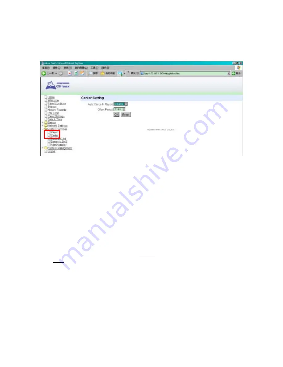
7.3. Center 

This is for you to set Auto-Check-in Report & Offset Period. 

Step 1.

 Click 

on 

System Settings

 and select the submenu 

Center

 and the following screen 

will be displayed. 


Step 2.

  Click on the 

V arrow

 to select the 

Auto Check-in Report

 and/or 

Offset Period


Step 3. 

Press 

OK

 to confirm all the latest updated parameter value.   

z


Auto Check-in Report 

This is to select whether the Control Panel needs to send check-in reporting to the Central 
Station automatically, and to select the time interval between check-in reports. 

z


Offset Period 

This is to set the time delay before the first 

Auto Check-In

 report to be made.     

After power is supplied or re-supplied to the Control Panel, a test report will be sent to the 
Central Monitoring Station (CMS) based on the Offset Period. This is used to test whether 
the CMS is able to receive the report from the Panel accurately. 

After this test report is sent, the Control Panel will then send regular reports based on the 
setting of the Auto Check-in Report.     

For example, if 

Offset


Period

 is set to 2 Hours, and 

Auto Check-in Report

 is set to 3 

Days, the Control Panel will transmit an event code 602 to the CMS after 2 hours, and 
then report 602 event code periodically at a regular intervals of 3 days.   


Summary of Contents for CTC-1745

Page 1: ...D D 31 Dec 08...

Page 2: ...___________________ 10 7 2 Mobile______________________________________________________________ 14 7 3 Center______________________________________________________________ 16 7 4 Code Setting ________...

Page 3: ...___________________ 44 11 1 Network ___________________________________________________________ 44 11 2 Wireless Setting Only for Wi Fi version ________________________________ 45 11 3 UPnP___________...

Page 4: ...burglar images with any trigger 2 Application Overview 2 1 Identifying the Parts Area 1 status LED Dual Colour Red Green z RED LED ON indicates that the Area 1 is currently in Arm Mode z RED LED FLASH...

Page 5: ...is fault in the system z LED OFF indicates that the system is normal operation mode Internal Buzzer Standing Base Learn Button Use Learn Button to locally learn Remote Keypads KP 9 KPA 9 into the pan...

Page 6: ...z When the battery is fully charged it can provide back up power for a period of about 10 hours It takes approximately 48 hours to fully charge the battery N NO OT TE E If the AC power is missing and...

Page 7: ...nternet connection cable into the Internet Jack on CTC 1745 Plug in the other end of the enclosed Internet cable into your Internet Router port With Wired Connection Once the Internet Set up is succes...

Page 8: ...p 4 Double click on the FinderV1 3 to initiate the installation Step 5 Click Next to re name the shortcut folder if no renaming is required please click Next to get ready for the installation process...

Page 9: ...igure Setting The Configure setting is for you to enter the Internet data manually Step 1 Click on Configure Setting the following window will display Step 2 Enter the internet data and the CTC 1745 s...

Page 10: ...onnection double click on Internet Explorer icon to initial its webpage Under Address section highlighted in RED enter CTC 1745 s IP address for example http 192 168 1 198 and click GO You will enter...

Page 11: ...9 Step 3 Enter the User name Password and then click on OK User Name admin Password admin1234 The screen enters the home page of the Alarm Panel...

Page 12: ...Numbers If BOTH IP Tel numbers are set as either First Priority or Second Priority the reporting will start with IP one first Step 1 Click on System Setting and then Report the following screen will...

Page 13: ...unt Number The Guardian Code has the same authorization as the PIN Code It is designed for the patroller of the Central Station For example if the Account Number is set to 6327 then the Guardian Code...

Page 14: ...g For example Area1 Panic Alarm 4 Priority 1 First Priority The system must report to this Tel number first in priority order and successfully If more than one set of Tel number and or IP address is s...

Page 15: ...1st time IP 1 5th time IP 2 1st time IP 2 5th time GPRS 1 1st time GPRS 1 5th time GPRS 2 1st time GPRS 2 5th time TEL 1 SMS Text 1st time TEL 1 SMS Text 5th time TEL 2 SMS Text 1st time TEL 2 SMS Te...

Page 16: ...Access Point Name It is the name of an access point for GPRS Please inquire your service provider for an APN When APN is set the system becomes valid for internet connection 2 User GPRS It is the Log...

Page 17: ...requires a different Keyword and Header in order to differentiate from each other 1 SMS Keyword Set a personalized Password to allow Remote Controlling via SMS Text message feature A maximum of 15 ch...

Page 18: ...ports z Offset Period This is to set the time delay before the first Auto Check In report to be made After power is supplied or re supplied to the Control Panel a test report will be sent to the Centr...

Page 19: ...programmed individually Click on button to scroll down the selection you can select area 1 or area 2 Step 1 Key in your preferred 4 digit Duress Code Master Code and or Temporary Code Step 2 You can a...

Page 20: ...he temporary Code is ONLY valid for one access per arming and disarming Afterwards the Temporary Code will be automatically erased and needs to be reset for a new Temporary user The Temporary Code con...

Page 21: ...19 7 5 Dynamic DNS It is used to get your real public IP address on the internet The information is already pre set into the system Factory default is Dynamic DNS Server checkup dyndns com Port 80...

Page 22: ...d Set the new Adminstrator Log in name for accessing this Web Page To SET the ADMINSTRATOR NAME and LOG IN PASSWORD BEFORE SETTING Please note the Caps for your Log in Name and Password Step 1 Enter t...

Page 23: ...1 Under the Add Sensor menu move the cursor to Area box then choose in which area the device should be learnt Step 2 Select a Zone number for this device Step 3 Move the cursor to Sensor ID box Step...

Page 24: ...ical Emergency or Water z For PIR Sensor you are requested to select the device attribute from Burglar Home Omit Home Access or Entry Zone z For Remote Controller you are requested to select the devic...

Page 25: ...is active at all times and does not have to be armed or disarmed An event code of 130 will be reported Fire F z The Fire Door Contact is active at all times and does not have to be armed or disarmed...

Page 26: ...stant Burglar Alarm No Response Instant Burglar Alarm No Response N Home Omit NO No Response Instant Burglar Alarm No Response Instant Burglar Alarm No Response No Response Instant Burglar Alarm No Re...

Page 27: ...Instant Medical Alarm Water W Instant Water Alarm Instant Water Alarm Instant Water Alarm Instant Water Alarm Instant Water Alarm Instant Water Alarm Instant Water Alarm Instant Water Alarm Set Unset...

Page 28: ...ted in red under Sensor Information section Step 2 You are then requested to set a new Sensor name Sensor Attribute Step 3 Press OK to save your new changes The device editing procedure is now success...

Page 29: ...ing in ONE WAY DEVICES z RJ 11 Programming Cable Recommended Plug in the external RJ 11 programming cable to the Programming Jack of the control panel and connect it to the Programming Jack of KP 18 E...

Page 30: ...is 0000 followed by the key A long beep will be emitted on KP 9 KP A9 with Green LED on Step 6 Put KP 9 KP A9 in Add Device mode and it will show Push button on device to add Step 7 Press key followe...

Page 31: ...p object to slide SW3 SW4 on the SR 15 DIP switch block to program your desired alarm period see operation manual of SR 15 Step 3 Put the KP 18 into Add Devices mode the screen will show Push button o...

Page 32: ...evice is to be bypassed in next the Away or Home Mode N NO OT TE E If a sensor is bypassed then the Control Panel will not respond to its triggering in Arm mode The bypass setting is effective for onl...

Page 33: ...to Arm Home Day Home Night Home Disarm the system mode remotely for both Areas A green radio button indicates its current system mode Step 1 Click on Panel Condition and the next screen will be displa...

Page 34: ...is required on CTC 1745 IP Panel User PIN code 2 6 are deactivated by factory default All 12 User PIN Codes are used to regularly arm disarm the system and are allowed to access the Programming mode a...

Page 35: ...smit reporting s to notify the Central Monitoring Station z Delete Except User 1 which can t be deleted in any way User 2 3 4 5 and 6 PIN code can be deleted by clicking the Delete box Delete With a t...

Page 36: ...down period it is allowed to use correct PIN code to disarm the alarm and the alarm reporting is not sent On the other hand if the correct PIN code is not entered during the period Control Panel raise...

Page 37: ...0 sec in 10 sec increments 5 Alarm Length This is for you to select the built in siren duration when an alarm is activated Options are Disable no siren alarm and 1 min to 15 min in 1 min increments z...

Page 38: ...ceive the check in signals from the devices to indicate their proper functioning The PIR sensor Door Contact Water Sensor or Smoke Sensor after installed will transmit a periodic supervision signal at...

Page 39: ...een tick will disappear Press OK to confirm Date This is for you to set the current month date Time This is for you to program the current time to be displayed hour minute Time Zone Choose your time z...

Page 40: ...e your CTC 215 IP Camera has completed its set up before it can be used with this function 8 1 Cameras Step 1 On System Web Page click on Surveillance then Camera Camera Information will be displayed...

Page 41: ...he particular CTC 215 IP Camera that you wish to include Step 5 Tick the Capture Images check box if you want this camera to capture alarm images once the system has been triggered If it is not select...

Page 42: ...sers should select the devices located closer to the IP Camera Users can select different learnt in devices for one IP Camera maximum 80 devices but the selected devices should be set in the same area...

Page 43: ...er and Netscape users Step 1 Click on Viewer under Surveillance to see the 24 Hour live show of each camera TO USE BELOW FEATURES PLEASE MAKE SURE YOU HAVE ALREADY INSTALLED JAVA AND ACTIVE X SOFTWARE...

Page 44: ...d Events to see Burglar images taken by any CTC 215 IP Camera linked to alarm triggered devices Step 2 Click on View in the View column to see the image gallery The numbers in the Status column indica...

Page 45: ...nnection Only one set of pre post alarm images can be stored in CTC 215 IP Camera i e if an alarm is triggered for a second time the second pre post alarm images will not be stored You are required to...

Page 46: ...not required This is only to be chosen if your Network environment supports DHCP It will automatically generate all information z Use the IP address You can also enter the Network information manually...

Page 47: ...D name Step 2 Select the Security Level of your Wi Fi connection The available ones are None WEP WPA and WPA2 N NO OT TE E If you don t know the Wi Fi SSID and or Security Level please contact your ne...

Page 48: ...etween ASCII or HEX 4 Key Index You are able to input 4 security keys This is in case you have more than 1 network that you can connect to Instead of having to enter the encryption key every time you...

Page 49: ...IP or AES 2 Passphrase z Site Survey 1 SSID Service Set Identifier is an identifier for the wireless network name that other devices can recognize 2 Site Survey This page will allow you to select a wi...

Page 50: ...transfer among networked devices in the home office and public spaces z Enable UPnP Device CTC 1241 supports UPnP Once this is selected you will be able to see this device via any UPnP discovery tool...

Page 51: ...displayed Step 2 Click on Browse and locate the latest Web firmware file in your PC Step 3 Click Apply to flash to the latest firmware It will take about 2 5 mins to load the file onto CTC 1241 Step...

Page 52: ...e displayed Step 2 Click on Browse and locate the latest Panel firmware file in your PC Step 3 Press Apply to flash to the latest firmware It will takes about 2 5 mins to load the file onto CTC 1745 S...

Page 53: ...ng down the S key Step 3 Release the S key when a tone is heard Test Mode will be displayed Step 4 Enter the following keys sequence STSTSTST OK Step 5 Press the key Step 6 All programmed parameters a...

Page 54: ...Priority Info General System Information Warning Finer System Information Error System Error Information Identiry and Message z The System Event log includes 9 Whenever the WAN IP is changed 9 Date T...

Page 55: ...h Date Time Hour Minute Sensor User and Activation cause of event z The Panel alarm log memorizes the last 30 Panel events including 9 All Alarm Events with Device ID 9 All Fault Warning Events from P...

Reviews: