Gardner Denver RSD Series, Instruction Manual
The ABB RSD Series Operating Instructions Manual is a comprehensive and user-friendly guide that provides step-by-step instructions for optimal usage. Download this invaluable manual for free from our website, and harness the full potential of your ABB RSD Series product.
Share
Download


Reviews:
No comments
Related manuals for RSD Series

D620
Brand: Qlima Pages: 84
AZ61H12DAB
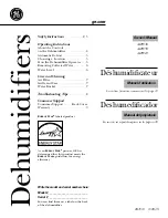
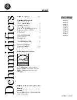
Brand: GE Pages: 32

HD451E
Brand: Haier Pages: 7

HD301
Brand: Haier Pages: 8

DM32EK
Brand: Haier Pages: 28
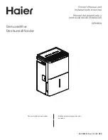
QPHR50
Brand: Haier Pages: 23

DM32EK
Brand: Haier Pages: 28

DH300
Brand: N'oveen Pages: 19
AHW30
Brand: GE Pages: 24
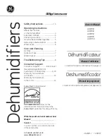
ADER30LN
Brand: GE Pages: 36

ZD30
Brand: Zenith Pages: 6
AD-200
Brand: DanVex Pages: 12

BT55
Brand: Nemaxx Pages: 47

100
Brand: Quest Engineering Pages: 6

100
Brand: Quest Engineering Pages: 26
APD Series
Brand: ACD Pages: 24

DE Series
Brand: Haier Pages: 28
D-Series
Brand: NANO Pages: 26


