- 6 -
9
4. Method of operations
4.1 Pump
The compressor unit of the VWZ is a fresh oil, once through lubricated, rotary vane type pump. The fl ow direction is from top to
bottom, so that any contamination in the suction stream or condensate is readily discharged.
4.2 Pressure relief valve
The spring loaded pressure relief valve is located between the LP and HP stages. The function of the valve is to prevent an over-
pressure occuring between the LP and HP stages when the suction pressure is atmospheric. This over-pressure would occur as
a result of the higher capacity of the LP stage, compared to the HP stage. With the valve open the gases pass directly into the
exhaust, by-passing the second stage. As the suction pressure reduces the pressure differential between interstage and exhaust
becomes insuffi cient to hold open the valve, which closes progressively. When the interstage pressure drops to atmosphere or
lower, then full two stage compression is in operation.
4.3 Oil lubrication
The bearings of the LP and HP stages and the gear wheels, each have their own separate oil lubrication supply.
The compression chambers of the vacuum pump are continually fed with a metered fresh oil supply, from an oil metering pump.
This oil is exhausted from the pump together with the gas stream and separated out.
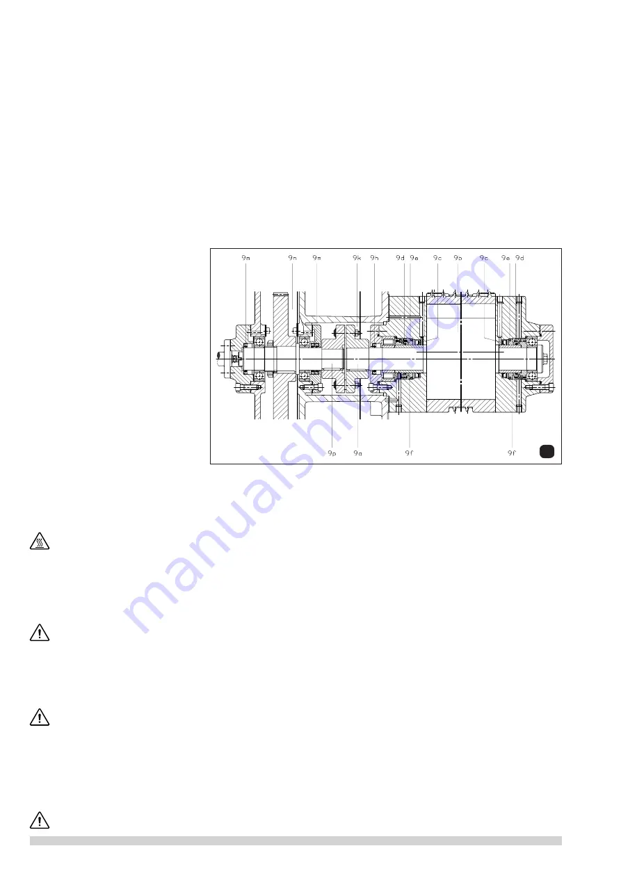
4.4 Shaft seals (fi g. 9)
Shaft sealing rings (9c) are fi tted on both
ends of the rotor shaft (9a) to seal of the
stage (9b). These sealing rings are mounted
on exchangeable shaft sleeves (9d, 9e)
together with the back up mechanical
seals (9f). A further shaft sealing ring (9h),
seals off the coupling area (9k) on the drive
side. The shaft sealing rings (9m) prevent
the leakage of oil from the gear box (9n)
along the gear shaft (9p).
5. Installation
5.1 Mechanical Installation
5.1.1 Mounting
(see data sheets D 111 + D 117)
Pumps that have reached operating temperature may have a surface temperature of more than 70°C depending
on a set temperature at the thermostat. Especially the cooling water jacket might be very hot. WARNING! Do Not
Touch.
The VWZ is vibration free so a special foundation fastening is not necessary. When positioning the pump, it is important to ensure
that it is mounted horizontally and that there is easy access for routine checking of instruments, topping up of oil and water sys-
tems and for repair work on the motor pump. A clearance of 0.5 m should be allowed to the nearest wall to ensure free entry (
E
)
and exhaust of the cooling air (
F
). The ambient temperature where the pump is installed should not exceed 40°C.
Further we recommend a clearance of approx. 0.3 m from motor and approx. 0.6 m to the nearest wall for maintenance.
The VWZ pumps can only be operated reliably if they are installed horizontally.
For operating and installation follow any relevant national standards that are in operation.
5.1.2 Suction Side
(see data sheets D 111 + D 117)
The suction pipework should be connected at (
A
) (standard ISO-Flange). This suction line should be as short as possible, but
if it is more than 5 m, than a larger diameter than that of the pump fl ange should be used. The pipe layout should be such that
there is no strain on the pump, if necessary use fl exible section. Appropriate separators should be fi tted to protect the pump from
suction of solid particles and liquids (see accessories).
Solid particles of more than 5 μm and liquid slugs are able to destroy the compressor stages.
5.1.3 Exhaust
(see data sheets D 111 + D 117)
If an oil mist separator is fi tted the exhaust pipework is connected at (
B
). If an oil mist separator is not required then the pipework
is connected directly at
B
. In this case the pipework should be laid so that it drains away from the pump. If it is necessary for
the exhaust pipework to rise, then a catchpot should be fi tted as near to the pump as possible, to collect condensate. This pot
should have drainage point of a diameter of at least
1
/
2
“. It is also advisable to fi t a level switch below the pump exhaust level to
operate an automatic drain valve or a shut down sequence so that a build of condensate which could fl ow back into the pump
is prevented.
The exhaust resistance within the pipework should not exceed 0.3 bar overpressure.


