


13--8--625
Page 41
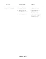
SYMPTOM
POSSIBLE CAUSE
REMEDY
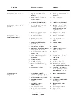
Compressor starts too slowly
1.
Wye Delta switch time set
1.
Contact your Gardner Denver
too long.
distributor.
2.
Minimum Pressure/Check
2.
Repair or replace.
Valve is faulty.
3.
Supply voltage is too low.
3.
Check the supply voltage.
Compressor runs unloaded
1.
Volume of compressed air
1.
Check the volume of the
too often
system too small.
piping and air receivers.
An additional air receiver
may be required.
2.
Pressure range too narrow.
2.
Extend pressure range
Compressor is low on
1.
Restricted air filter.
1.
Clean or replace filter.
delivery and pressure
2.
Sticking inlet valve.
2.
Inspect and clean inlet
valve.
3.
Minimum pressure valve
3.
Replace valve.
stuck closed.
4.
Oil separator clogged.
4.
Replace
5.
Intervals of moisture separator
5.
Check the setting in the
drainage incorrectly set.
Air Pilot controller
6.
Condensate drain solenoid
6.
Replace.
valve is faulty.
7.
Leaks in the compressed
7.
Check for leaks, fix any
air system.
leaks found.
8.
V--Belts broken.
8.
Replace.
9.
V--Belts slipping.
9.
Test belt tensioning.
10. Pressure limits incorrectly
10. Check/correct pressure
set.
limits in the Air Pilot Controller.
11. Aftercooler is frozen.
11. Thaw out. This machine
cannot operate in temper--
ature below 32
_
F (0
_
C).
High discharge air
1.
Thermostatic mixing
1.
Repair or replace valve.
temperature
valve stuck open (in bypass).
2.
Dirty or clogged cooler face.
2.
Clean cooler.
3.
Insufficient cooling
3.
Provide unrestricted supply
air flow.
of cooling air.
4.
Clogged oil filter or
4.
Replace filter or clean
cooler (interior).
cooler.
5.
Low compressor oil.
5.
Add oil to proper level.
6.
Faulty temperature sensor.
6.
Repair sensor.
Summary of Contents for EFD-25 HP
Page 13: ...13 8 616 Page 4 DECALS 206EAQ077 212EAQ077 218EAQ077 211EAQ077 207EAQ077...
Page 14: ...13 8 616 Page 5 DECALS 216EAQ077 217EAQ077 222EAQ077 221EAQ077 208EAQ077...
Page 30: ...13 8 625 Page 21 FIGURE 4 4 COMPRESSOR RUNNING FULLY LOADED...
Page 32: ...13 8 625 Page 23 FIGURE 4 5 WIRING DIAGRAM 3 305865 Ref Drawing...
Page 33: ...13 8 625 Page 24 FIGURE 4 6 WIRING DIAGRAM 3 305979 A Ref Drawing...
Page 34: ...13 8 625 Page 25 FIGURE 4 7 WIRING DIAGRAM 3 305979 A Ref Drawing...
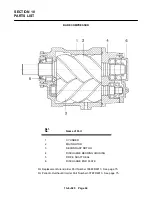
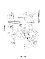
Page 54: ...13 8 625 Page 45 AIREND GROUP...
Page 60: ...13 8 625 Page 51 AIREND AND INLET FILTER ASSEMBLY...
Page 72: ...13 8 625 Page 63 COOLING GROUP...
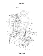
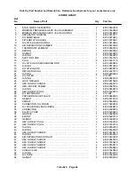
Page 74: ...13 8 625 Page 65 CONTROL SYSTEM ASSEMBLY AND MOUNTING...
Page 78: ...13 8 625 Page 69 CONTROL BOX 3 305979 A Ref Drawing...


