13-8-627 Page 38
8.
Align sheaves with a straight edge. (See “SHEAVE ALIGNMENT”).
9.
Assemble the guards.
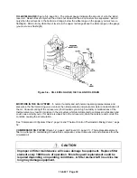
SHEAVE ALIGNMENT
The sheave alignment and belt tightening system consists of a hinged plate for the motor which is
supported between (2) posts and a slotted platform for the Tempest units. To achieve proper sheave
alignment the sheaves must be adjusted for both parallel and angular alignment. The alignment between
the motor and air-end sheaves should be confirmed with the use of a straight edge. If the sheaves are
properly aligned, the straight edge should touch the two outer edges of each sheave for a total of four
points of contact. Gaps between the outer edges of either of the sheaves and the straight edge indicate
sheave misalignment.
The airend sheave is set in the parallel and angular direction by mounting it on the air-end shaft that is
part of the Tempest unit that is bolted to the platform. The platform has been set in the parallel and
angular directions by its inherent design. The motor sheave is set in the parallel direction by sliding it on
the motor shaft to position it in line with the airend sheave. (Check for alignment with straight edge.)
Note
: It may be necessary to loosen the Tempest unit and slide it in the platform mounting slots to keep
the motor sheave fan blades in the correct position in the cooler orifice ring.
The motor sheave is set in the angular direction by means of (2) jack bolts and the hinged plate. To start
the angular alignment process check to make sure the locking nuts on the jack bolts are loose. The
motor sheave can be aligned in the angular direction to the same plane as the airend sheave by turning
down the jack bolts on one side or the other of the hinged plate. (Check for alignment with straight edge.)
It also may be necessary to use the nuts that are on the jack bolts to push up on one side or the other of
the hinged plate.
Note
: At this point it may also be necessary to make minor adjustments of the position
of the sheave on the motor shaft to get proper alignment. Once proper alignment has been obtained, lock
the sheave in place on the motor shaft; then the jack bolt lock nuts must be tightened. One set of nuts is
tightened down against the base to lock the jack bolts in place. The second set is locked down to
sandwich the hinged plate against the jack bolt heads. When lock nuts are in place, a final alignment
check should be made with the straight edge.
Note
: Any of the following actions will require the sheave alignment be checked and any or all of the
above steps repeated. (Initial start up at customer site, compressor change, motor change, unit
relocation, or when the belts are replaced.)
It’s important to note that the belts should not be over tightened. To check belt tension use a Gardner
Denver Belt Tension Gauge, Part Number 00543217. V-belt tension will drop after the first 8-24 hrs of
unit run time. Failure to check and re-tension the belts after the initial run-in period will result in belt
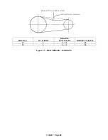
slippage and premature belt failure. Please see Figure 7-1, for proper belt tension.
CHECKING BELT TENSION
- Using a spring scale, apply a perpendicular force to each belt at the
midpoint of the span and measure the deflection. Correct deflection force and deflection are shown in
Figure 7-1. To tighten belts, merely increase the center distance.
NOTICE
When a new set of belts is installed on a drive, the initial deflection force should
be 1/3 greater than shown in Figure 7-1. Recheck tension frequently during the
first 24 hours of operation
Summary of Contents for Champion ROTORCHAMP EFD99A
Page 9: ...13 8 627 Page 2 Figure 1 2 COMPRESSOR ILLUSTRATION 300EFD797 A Ref Drawing...
Page 12: ...13 8 627 Page 5 DECALS 206EAQ077 212EAQ077 218EAQ077 211EAQ077 207EAQ077...
Page 13: ...13 8 627 Page 6 DECALS 216EAQ077 217EAQ077 222EAQ077 221EAQ077 208EAQ077...
Page 29: ...13 8 627 Page 22 Figure 4 3 WIRING DIAGRAM FULL VOLTAGE 300EFD546 C Ref Drawing Page 1 of 2...
Page 30: ...13 8 627 Page 23 Figure 4 4 WIRING DIAGRAM FULL VOLTAGE 300EFD546 C Ref Drawing Page 2 of 2...

