background image


© 2019 Garderos GmbH 


12/21 

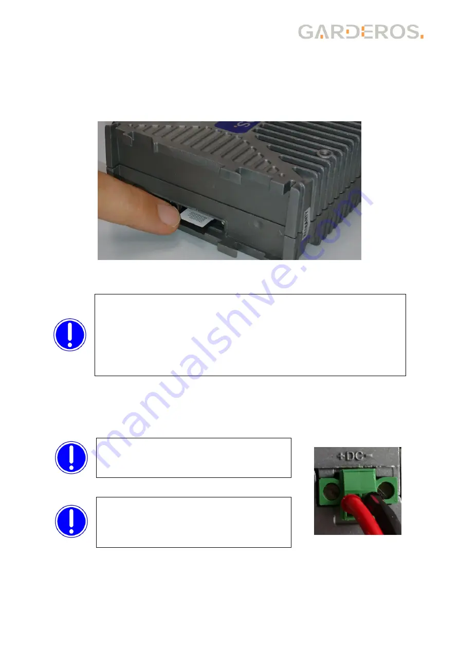
5.2.2  Inserting the SIM-card 

Insert the SIM card into the SIM tray and push the SIM tray back into the router as 
shown in the following picture. Take care to correctly push the SIM tray into the SIM 
card  tray  holder.  The  SIM  card  tray  fits  below  the  tray  holder  and  may  slip  into  the 
router, if not put into the right position.  


Put back the DIN rail mounting kit after that into the initial position. 


5.3  Powering up the router 

This device has no power switch. To power it on, just connect DC power (12-60V) to 
the router. 


Before  starting  the  R-3700  an  antenna 
must  be  connected  to  the  M1  connector 
for  models  containing  a  WWAN  modem, 
otherwise the router may be damaged. 


Remove  the  WWAN  settings  of  the  router  before  inserting  a  new 
SIM  card.  Otherwise  the  router  might  try  to  establish  the  WWAN 
connection  with  the  previous  settings,  and  an  incorrect  PIN  might 
cause the SIM-card to be locked. 
Only  insert/remove  the  SIM-card  when  the  router  is  powered  off! 
Use  thermo  resistant  Mini-SIM-cards  for  up  to  80°C  (ask  your 
cellular operator for industrial SIM-cards). 


Connect  VCC  to  +  and  0V/GND  to 

–  as 

marked  on  the  front  plate.  Otherwise  the 
router might be damaged! 

Summary of Contents for R-3700 Series

Page 1: ... R 3700 Series Ruggedized router IP42 with 2 RJ 45 10 100 1000 BaseT Ethernet interfaces 1 RJ 45 RS 232 serial interface management RS 485 1 DSUB 9 female RS 232 full 1 or 2 integrated WWAN modems 2 3G 2 3 4G CDMA 1 or 2 WLAN 802 11n a b g ac optional ...

Page 2: ... as described in this document and make sure to comply with safety distances Unauthorized persons must not get nearer than 60cm to the GSM UMTS LTE antennas Unauthorized persons must not get nearer than 7cm to the WLAN antennas Depending on the router type the antenna and configured networks the safety distances may be smaller Use the calculations in the Annex to calculate the minimum safety dista...

Page 3: ...3745 2 1 1 1 2 R 3747 2 1 1 1 1 R 3748 2 1 1 1 1 R 3749 2 1 1 2 R 3751 2 1 1 1 1 1 R 3752 2 1 1 1 2 R 3755 2 1 1 1 2 R 3757 2 1 1 1 1 R 3758 2 1 1 2 R 3759 2 1 1 2 R 3771 2 1 1 1 1 R 3773 2 1 1 2 1 R 3777 2 1 opt 1 1 The router type can be identified by the serial number of the router The type is coded into the first 5 characters of the serial number 2 2 Included in delivery of Garderos R 3700 Sta...

Page 4: ...clip Mount the router on a DIN rail as shown in the following drawing Insert the upper metal hook to the DIN rail first and then push the plastic holder into the bottom part of the DIN rail until it clicks in see picture The IP protection in this position is IP 41 For unmounting push the router up then remove it from the top of the DIN rail first ...

Page 5: ... The DIN rail clip will be attached to the router using two M4 screws The IP protection in this position is IP 42 Insert the upper part of the clip to the DIN rail then push the router down and insert the DIN rail clip to the rail on the lower part For unmounting push the router down and remove the lower part of the clip from the DIN rail first ...

Page 6: ...otection as shown in the following image 3 1 4 Grounding Grounding is not required for router operation but it improves the EMI characteristics and is mandatory to comply with the standard IEC 61850 3 For grounding attach a 1 5mm ground cable with a 0 8 x 2 8mm flat connector to the spade connector on the R 3700 router as shown in the following picture ...

Page 7: ...ks during fetching and executing the router configuration and is permanently lit when the configuration of the device has been completed W1 green Depending on the type of the WWAN link this LED signals the state of the link The LED is off when no WWAN connection is active and is lit while at least 1 WWAN connection is active W2 green Is lit when the integrated WLAN interface is active Eth link gre...

Page 8: ...rial components eth0 RJ 45 jack for 10 100 1000 BaseT Ethernet eth1 RJ 45 jack for 10 100 1000 BaseT Ethernet M1 Main 1 antenna connector See 3 3 3 for description A1 Auxiliary 1 antenna connector See 3 3 3 for description M2 Main 2 antenna connector See 3 3 3 for description A2 Auxiliary 2 antenna connector See 3 3 3 for description M3 Main 3 antenna connector See 3 3 3 for description RS 232 Opt...

Page 9: ...3 Antenna connectors Depending on the router type the antenna connectors M1 A1 M2 A2 and M3 are used for different antenna connections e g a 4G or a WiFi card or they do not exist on the router The connectors are always SMA female for WWAN antennas and RP SMA for WiFi antennas Login to the router and use the command R3700 show hardware connector to show the assignment of the antenna connectors 3 3...

Page 10: ... can be downloaded from a web server for central configuration management Interfaces to other systems via APIs HTTPS Configuration API RADIUS authentication NTP SNMP The GRS documentation is available online at https www garderos com techsup Username and password for login to the support web are available from your Garderos sales representative The documentation contains a detailed description of ...

Page 11: ...IM card must always be inserted into slot SIM 1 which is intended for the modem wwan0 For routers with 2 WWAN modems e g R 3757 the SIM card for the WWAN modem called wwan0 must be inserted into SIM 1 the SIM card for the modem wwan1 into slot SIM 2 To access the SIM card slots remove the DIN Rail mounting kit by pushing it to the top Always put back the DIN rail mounting kit after inserting the S...

Page 12: ... power it on just connect DC power 12 60V to the router Before starting the R 3700 an antenna must be connected to the M1 connector for models containing a WWAN modem otherwise the router may be damaged Remove the WWAN settings of the router before inserting a new SIM card Otherwise the router might try to establish the WWAN connection with the previous settings and an incorrect PIN might cause th...

Page 13: ... W2 Is lit when at least 1 WLAN interface is active 5 4 Login The Garderos R 3700 can be managed via a serial console Connect your computer to the router s CON RS 485 port using an RJ 45 serial console cable Use the following settings Bits per second 115200 Data bits 8 Parity N Stop 1 Flow control None Log in with the following credentials User name root Password g42pnuMN Find online documentation...

Page 14: ... temperature range Same as operating temperature range WWAN optional 2G 3G 4G CDMA see datasheet for details Network interfaces 2 RJ 45 10 100 1000 BaseT Ethernet autosensing auto MDI X WLAN optional 802 11ac a b g n 802 11 b g n Serial ports 1 RS 232 mgmt 1 RS 485 1 RS 232 optional Ingress protection IP42 IEC protection class 3 Conformity CE FCC 61850 3 criteria for EMI immunity RoHS Max temperat...

Page 15: ...tion file To change the WLAN TX power see the online documentation for the configuration parameter hardware wifi tx power The following calculation shows how to calculate the TX power that must be configured in the router to comply with the regulatory restrictions Calculate the total antenna gain The antenna gain consists of Losses inside the router This is a static value of 0 3dB Antenna gain tak...

Page 16: ...EG Calculate the output power on the antenna from the configured TX power on the router and the total antenna gain Output power Configured tx power Total antenna gain Output power for the example above Output power 16dBm 0 3dB 4dBi 0dB 19 7dBm Round up the value 20dBm and select the safety distance from the table below 2 4GHz 5 5GHz Output power Safety dist Output power Safety dist 18dBi 2 2cm 18d...

Page 17: ...3 5dBm 24dBm LE910 EU V2 33 5dBm 24 5dBm 24dBm LE910 EU1 33 5dBm 24dBm LE910 EUG 33 5dBm 25dBm 25dBm MC7430 24dBm 24dBm MPN200 25dBm WPD 600N 23dBm The gain and loss in the antenna and antenna cables also need to be taken into account to get the output power relevant for the safety distance Calculate the total output power on the antenna This value is calculated from Output power for each technolo...

Page 18: ...culate the output power for your router antenna setup for all frequencies Then read the safety distances from the following table for each of them Round up the output power and round down the frequency to one of the values from the table The highest value shown in the table is the safety distance that you should comply to Output power 450MHz 700MHz 800MHz 900MHz 1500MHz 1800MHz 2GHz 20dBi 6 0cm 4 ...

Page 19: ...2 4cm 17 8cm 16 8cm 16 8cm 16 8cm 6 0cm 9 5cm 7 5cm 0dB 28 2cm 22 4cm 21 0cm 21 0cm 21 0cm 7 6cm 11 9cm 9 5cm 2dB 35 4cm 28 2cm 26 6cm 26 6cm 26 6cm 9 6cm 15 0cm 11 9cm 4dB 44 6cm 35 4cm 33 4cm 33 4cm 33 4cm 12 0cm 18 8cm 15 0cm 6dB 56 1cm 44 6cm 42 0cm 42 0cm 42 0cm 15 1cm 23 7cm 18 8cm This simplified calculation can only be used if the antenna gain is equal for all frequencies or if the gain is...

Page 20: ...en disposing of the device This device must not be disposed together with household waste The Garderos R 3700 contains a CR 2032 battery which must be removed before disposal The battery can be removed in the following way Disconnect the device from the power supply Open the device by using a screw driver Remove the screws of the router main board by using a screw driver The battery is located in ...

Page 21: ... GmbH 21 21 Garderos GmbH Support Team T 49 89 189306 50 F 49 89 189306 98 E support garderos com Garderos GmbH Balanstr 55 D 81541 München Germany T 49 89 189306 0 F 49 89 189306 98 E info garderos com Novmber 2019 ...

Reviews: