3
ASSEMBLY
11. Carefully separate end plate from housing and tap out
bearings (9), lip seals (12), labyrinth seals (51) and
retainers (219).
12. Clean all parts for inspection if there has been any
metal to metal contact. Please consult your distributor
or factory for full specification sheets. NOTE: Rotors,
sideplates, body, bearing, journals can be re-
manufactured. Inspect timing gears for wear and
pitting. Factory bearings and seals should be
installed.
13. It is important to try to determine cause of failure, i.e.,
over-speed, pressure, lack of lubrication, etc., as it may
necessitate changes in operational procedure, to ensure
longer machine life.
1.
Drain oil from both covers by removing magnetic drain
plugs.
2.
Mark all parts with a center punch so that they can be
reassembled in same position (rotors, and plates,
housing and cover).
3.
Remove key from shaft.
4.
Remove oil slinger (20) and retainer plates (14) on
drive end sideplate.
5.
Install a pair of gear plates p/n 530061204, to each
bearing bore. Alternately turn two 2-ton, 2-jaw pullers
(CG240) to remove end plate (4) from rotor housing (3).
Tap out roller bearings (10), seals (12) and (51), seal
retainer (219).
6.
Turn unit around and remove bolts and washers (26 &
27) Tap non-drive end cover (7) with mallet to break
sealant and remove.
7.
Remove bolts and washers (29 & 25) using 7/8" socket.
Replace bolts in end of rotor to protect threads when
using puller.
8.
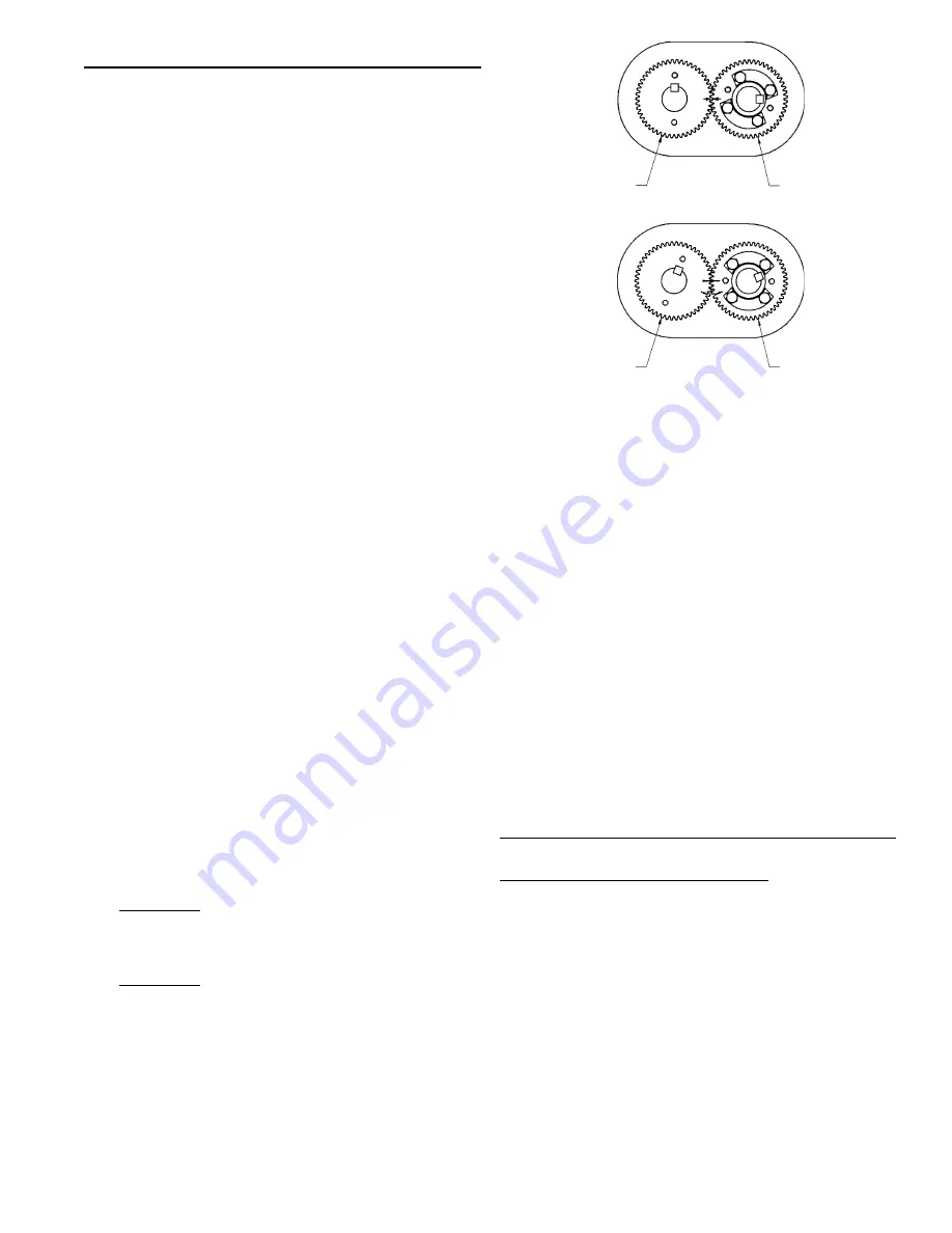
Position the blower with the driven gear on the right.
Align the timing gears for pulling by first matching the
timing marks on the gears. See Fig. 1A. Turn the drive
gear clockwise three teeth and mark a matching
reference line on each gear as shown in Fig. 1B. The
rotor lobes are now in their most open position. Using
a puller, CG240, the driven gear (left hand helix) may
now be removed without jamming the rotors. This gear
is in two parts--the gear rim and hub. It is not necessary
to disassemble. Do not allow the gears to move from
the matched reference line while pulling. Use a light
rocking motion while pulling the gear to ensure that the
lobes have not jammed.
Remove drive and non-drive gears. It is necessary to
remove keys from rotor shafts so that the gear plates
can be fitted for removing rotors from sideplates.
WARNING: Failure to properly pull the gears could
result in damage to rotor keyways or a bent rotor
shaft. Rotors must be free when pulling. If machine
is locked up, pull both gears simultaneously.
WARNING: Discard gear retaining bolts after
disassembly. These bolts are installed with
permanent Loctite and may fail if reused.
9.
Remove cap screws (61), washers (62), oil deflector
(15) and bearing lock plates (14).
10. Bolt gear plate p/n 530061204, with M6-70mm hex
head screws p/n 124006070, to side plate. Then use
puller, CG240, to press a rotor out of the sideplate.
Repeat process for other rotor.
DISASSEMBLY
Fig. 1A
Fig. 1B
TIMING MARKS ADVANCED 3 TEETH
(REFERENCE MARKS ALIGNED)
DRIVE GEAR
DRIVEN GEAR
TIMING MARKS MATCHED
DRIVEN GEAR
DRIVE GEAR
Preparation of End Plates for Assembly
1.
Make sure all parts are clean and free of any nicks or
burrs caused by disassembly.
See page 10 for seal pressing tools.
2.
Press labyrinth seals (51), using tool p/n 530061202,
with step facing up, into both end plates (4 & 5). Press
retainer downward with cupped side down until firmly
seated on top of labyrinth seal.
3.
Coat O.D. of lip seals (12) with Permatex #2 or
equivalent, and press into end plates, using tool p/n
530061203, with the lip facing upward until seated.
Lubricate lip seal with grease.
Summary of Contents for D807
Page 1: ......
Page 3: ......
Page 6: ......
Page 7: ......
Page 8: ......
Page 9: ... Available through Gardner Denver Inc ...
Page 10: ...WELD ALL AROUND ...
Page 11: ...3 HOLES EQUISPACED 5 HOLES EQUISPACED COMMON HOLE ...
Page 13: ......


