


PP520 LED lighting controllers - User Manual
8
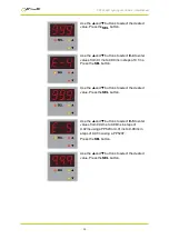
Connections
All connections to the 520 (except Ethernet) are made on screw terminals
at one end of the case (see below).
The screw terminals have the following connections:
Screw terminal ID
Function
TRIG1–
Channel 1 trigger input
TRIG1+
LED1+
Channel 1 lighting output
LED1–
PSU+
Power
PSU–
Power supply −
LED2−
Channel 2 lighting output
LED2+
TRIG2+
Channel 2 trigger input
TRIG2−
—
21
—