TR-RC1xx - User Manual
7.2
Triggering
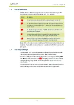
Trigger pulses should have a minimum pulse width of 2µs. You can set the
sense of the TR-RC trigger input. Do this by setting the P flag from the front
panel (see
Section 10.2, Front panel commands
), the web page (see
Section 9, Webpage configuration
) or the
RE
command (see
). The effect of setting the P flag is summarised
below:
Mode
P Flag
Output
Continuous
Unused
Output is on.
Switched
P Flag = 1
Output is
off
when trigger is off,
Output is
on
when trigger is on.
P Flag = 0
Output is
on
when trigger is off,
Output is
off
when trigger is on.
Pulsed
P Flag = 1
Pulse is triggered on rising edge.
P Flag = 0
Pulse is triggered on falling edge.
Note:
The P flag inverts the sense of the trigger.
7.2.1
Trigger input options
You can connect the following types of trigger to the Smart Input:
3V to 24V voltage source
Any voltage between 0V and 0.9V
is taken as logic 0.
Any voltage between 3V and 24V
is taken as logic 1.
TTL signal
You can connect a TTL signal to
the TR-RC’s input. However, a
3.3V TTL signal only works if it can
drive 8kohm without dropping
below 2.7V.
If the P flag is set to ‘1’, the TR-RC
output turns on when the TTL
driver goes HIGH. To reverse this,
set the P flag to ‘0’ (see
).
—
13
—


