background image


GarageSmart

TM  

User’s Manual 

15


Installation 


Installation and wiring 

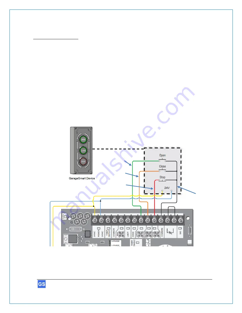
Installation of a GarageSmart GS100-CR is for controlling and monitoring commercial garage 
doors (typically found in businesses or factories), that have a 3-button wall mounted pushbutton 
(in which each pushbutton individually opens, closes and stops the garage door).  
 
In existing installations, the GS100-CR will replace your existing 3-button mechanical controller 
but it can also be added as a second door controller. 
 
For cabling, regular Cat 5 Ethernet wire (or equivalent) is recommended to use, as this wire is low 
cost, readily available and already contains 4 twisted pairs of wire (for 

OPEN

CLOSE

STOP

COM

, and 

24VAC/DC

 power connections), making installation from the garage door motors 

control box to the GarageSmart

™ 

device faster and easier. 

 
Depending on the application, additional parts may be required for proper installation. 


Existing Garage Door Opener Control Board  

(Example only) 

Com. Wire            

Stop Wire             

Open Wire             

Close Wire             

Isolated 

16-24VAC or 16-24VDC 

power supply 

Summary of Contents for GS100-CR

Page 1: ...GarageSmartTM User s Manual 1 User s Manual English US Version 0 17a For use with models GS100 CRS100N...

Page 2: ...t any time without prior notification This manual nor any parts thereof may not be reproduced for any purpose whatsoever without the express written consent of GarageSmart All technical specifications...

Page 3: ...rt Account Online Control Panel 11 Router Security Configuration 12 Installation 15 Installation and wiring 15 Alternate Mounting 22 Wi Fi Setup 24 Configure the GarageSmart Device to a secure Wi Fi n...

Page 4: ...4 GarageSmartTM User s Manual Technical Specifications 41...

Page 5: ...rk uses when connected to your router IP Address A unique string of characters that identifies each computer using the Internet Protocol to communicate over a network Gateway Address An IP address tha...

Page 6: ...discharging any static buildup on yourself To discharge yourself touch a grounded metal object such as conductor an earth grounded metal enclosure CAUTION Do not get the GarageSmart device wet or exp...

Page 7: ...liable for the accuracy of the information contained in this manual on its websites in its apps or for damages resulting from the use of the GarageSmart device this manual websites or apps Trademarks...

Page 8: ...pport page On this page you can Reset your account password Find warranty information Send an e mail to GarageSmart customer service Faqs on the most asked questions and answers E mail To ensure a tim...

Page 9: ...allows you to grant remote access with the use of a Master Key to as many users staff members employees etc as needed Customized individual schedules are also available by providing unique Remote Keys...

Page 10: ...cluded Your GarageSmart device comes with the following Welcome Letter Optional Parts and Accessories The following parts and accessories are available and can be purchased by contacting GarageSmart o...

Page 11: ...net account_setup html 2 Enter in all required information on the Account Setup page including the Mac Address and Device ID from the back of the GarageSmart device 1 3 Once a GarageSmart account has...

Page 12: ...ess in the Troubleshooting Help section of this manual 2 Under your routers Port Forwarding settings add the following information 3 a IP Address Select an available IP Address b Start Port Select 313...

Page 13: ...outer 1 Every routers login and Port Forwarding process is different from one another If you do NOT have access or know how to login into your router or add port forwarding to your router then refer t...

Page 14: ...evice Device Name GarageSmart Mac Address Port IP Address Gateway Address 1 Bay F1 843dd5e9ca30 31301 192 168 0 201 192 168 0 1 2 Bay F2 843dd5e9c874 31302 192 168 0 202 192 168 0 1 3 Front 843dd5e9c6...

Page 15: ...al controller but it can also be added as a second door controller For cabling regular Cat 5 Ethernet wire or equivalent is recommended to use as this wire is low cost readily available and already co...

Page 16: ...ing screws not included secure the GarageSmart GS100 CR to the wall using the mounting holes as shown below 3 Choose the best and most practical location to install the GarageSmart Sensor The sensors...

Page 17: ...erminal block using a screw driver as shown below Sensor Wires Wires connect to the OPEN CLOSE STOP and COM terminals of the garage door motor control board See the wiring diagram at the beginning of...

Page 18: ...mart device by connecting to the AUX NO AUX NC and AUX COM pins Wires connect to the garage motor control board power terminals See the wiring diagram at the beginning of this section for further info...

Page 19: ...pressing and holding the STOP Button for 5 seconds After 5 seconds has passed the NO NC AUX switch will then be energized and change state with the Buzzer sounding simultaneously for as long as the S...

Page 20: ...D of the GarageSmart device illuminates when the door is Closed and is off when the door is Open 10 Carefully plug the 11 pin connector from top PCB into the J2 connector of the bottom PCB 11 Pin Conn...

Page 21: ...GarageSmartTM User s Manual 21 11 Close and secure the cover of the GarageSmart device using the 4 screws that were removed from step 2 above as shown below Screw Screw Screw Screw...

Page 22: ...rom the wall 2 Remove the cover of the GarageSmart device and using screws not included secure the GarageSmart GS100 CR with the buzzer towards the top of the enclosure to the wall using the mounting...

Page 23: ...nual 23 4 Rotate the bottom PCB as shown below then re install the 4 PCB screws and connect the buzzer connector to the J3 terminal on the PCB 5 Continue with the installation and wiring per the secti...

Page 24: ...ecome a Wi Fi Access Point for device configuration purposes and will indefinitely broadcast its unique SSID in the form of GarageSmart_80_xxxx 3 For security reasons the GarageSmart device will stop...

Page 25: ...work has been established your cellphone tablet or computer may show Internet may not be available or a similar phrase as this is normal Continue by opening your web browser and typing the following a...

Page 26: ...that was filled in with the Port Forwarding settings from within the Router Security Configuration section above find the row with the Mac Address that matches the Mac Address of the GarageSmart devi...

Page 27: ...s will always remain constant within the router keeping the GarageSmart device online at all times 3 At the end of the GarageSmart Wi Fi Network name SSID the first group of numbers usually 2 or 5 num...

Page 28: ...trol and monitor a GarageSmart device the User a Remote Key and Schedule for that User must be added to your account all of which can be achieved by using the Online Control Panel An Installer Mode fe...

Page 29: ...s to control multiple doors one at a time or even simultaneously Further information on the differences between Classic and Advanced can be found within the Online Control Panel Manual that can be fou...

Page 30: ...urrent selected device every time the app opens restarts This feature is only available when App Mode is set to Classic Screen Size Residential View Changes the size of the residential Open Close imag...

Page 31: ...d 2 9 Click the Exit button within the app Controlling Garage Doors using the GarageSmart App The GarageSmart app has the capability of controlling either one door at a time or multiple doors Controll...

Page 32: ...ilable to the user Press and hold the OPEN button to open the door Press and hold the CLOSE button to close the door Press the STOP button to stop a door during movement CAUTION Verify and confirm the...

Page 33: ...geSmart devices Bay 1 Door and Bay 2 Door that are available for the user to control within the Warehouse location 2 Press and hold the Gray Box next to the first door that you want to control as the...

Page 34: ...ageSmart App will automatically retrieve and display the door status of the last door that was selected See the section Verify Garage Door Status using the GarageSmart App below for further informatio...

Page 35: ...currently selected The status of current selected door will be visible by a GREEN or RED halo around the OPEN or CLOSED buttons A GREEN halo around the OPEN button means that everything is Secured an...

Page 36: ...t The default Gateway Address of your router can be found using one of the following methods On the Router i Look for the Gateway Address at the back or bottom of your router On Windows ii Search and...

Page 37: ...red Repeat the procedure Configure the GarageSmart Device to a secure Wi Fi network verifying that all settings entered match your router settings AMBER 1 GarageSmart device is connected to the router...

Page 38: ...ove steps Factory Reset A factory reset can be performed on the GarageSmart device without having to remove the cover that will reset the Port of the GarageSmart device to its default Port 80 and clea...

Page 39: ...l board The website mobile site or app is showing the wrong status or always shows Open for my garage door s Visual inspect the GarageSmart sensor for any broken wires and make sure that the two senso...

Page 40: ...rs after being left open or have them close at a pre determined time of your choosing for example every night at 10 00PM for security Is the GarageSmart protected under any warranty Yes all GarageSmar...

Page 41: ...m 802 11g 17 dBm 802 11n 14 dBm Operation Wi Fi Range Typical Ranges 802 11b 115 feet indoors 802 11g 115 feet indoors 802 11n 230 feet indoors Typical ranges are dependent on the user s router transm...

Reviews: