background image


NC3502


Ver1.3


3


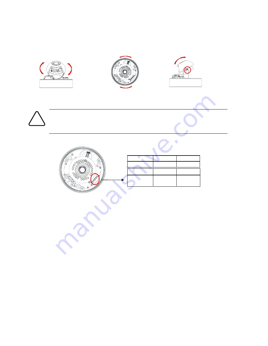
Step3.  Set the lens position 

1)


Remove


the


dome


cover.


2)


Set


the


lens


position


by


rotating


the


camera


gimbal;


to


pan,


rotate


the


reinforced


lower


body


of


the


gimbal;


to


tilt,


vertically


adjust


the


camera


gimbal.


Caution

!


Refrain


from


continuously


rotating


the


camera


gimbal


with


excessive


force


to


a


single


direction


as


it


is


attached


with


the


IR

LED


cable


inside


the


dome.


3)


The


figure


and


table


below


explains


the


lens


switch


settings.


SW1


SW2


SW3


PAL/NTSC

TELE


WIDE


SW4


SW5


SW6


FAR


NEAR


Auto

Focus


B.


To


pan,


rotate


the


lower


body


of


the


camera


gimbal


C.


Tilt


the


lens


by


vertically


adjusting


the


camera


gimbal


A.


To


adjust


lens


position,


rotate


the


camera


gimbal


Summary of Contents for ZN-DNT352XE-MIR

Page 1: ... the correct positions of all connectors refer to the following image below Make sure the polarity is correct Incorrect connection may cause malfunction or damage to the IP device Caution Power Adaptor Connector DC 12V Model design and appearance are subject to change without any prior notice Reset Button Output Configuration Switch Clamping Core This uses to prevent electromagnetic interference L...

Page 2: ...on the template paper and insert anchor blocks into the holes 3 Place the waterproof silicon band on the bottom plate of the device and make it align with screw holes 4 Place the camera body to the installation surface and match three alignment holes with three anchor blocks Then tighten the surface anchor studs 5 Connect all the required cables to the camera 6 Adjust the lens position 7 Place the...

Page 3: ...ain from continuously rotating the camera gimbal with excessive force to a single direction as it is attached with the IR LED cable inside the dome 3 The figure and table below explains the lens switch settings SW1 SW2 SW3 PAL NTSC TELE WIDE SW4 SW5 SW6 FAR NEAR Auto Focus B To pan rotate the lower body of the camera gimbal C Tilt the lens by vertically adjusting the camera gimbal A To adjust lens...

Page 4: ... streaming images on a web page using the device s default IP address 1 Convert the device s MAC address to the IP address Refer to the Hexadecimal Decimal Conversion Chart at the end of the manual The MAC address of the device is attached on the side or bottom of the device 2 Start the Microsoft Internet Explorer web browser and enter the IP address of the device 3 Web streaming and device config...

Page 5: ... device from the IPAdminTool s list and highlight the device s name 2 Right click the mouse and select IP Address IP Setup window appears 3 In the IP Setup s window information under Local Network information displays the user PC s network area information Those information need to be incorporated to the IP Address Subnet Mask Gateway and DNS boxes except the last 2 sets of IP Address which are to...

Page 6: ... web address is accessed the browser asks to install the ActiveX Click Allow 2 Setup exe installation link or pop up window appears depends on Microsoft Internet Explorer version Proceed with rest of setup installation 3 Follow the instructions of the dialog boxes and complete the installation Once the installation is complete start the web browser again and check if video stream is displayed in t...

Page 7: ...factory default setting all parameters including the IP address will be initialized For the Factory Default reset 1 Press reset button and hold for 5 seconds 2 Release the button when the green Power LED blinks at 150ms interval 3 The power LED button turns to red and wait for the system to reboot More Information To learn more about using other features of your devices refer to the manual which i...

Page 8: ... 58 88 7D 125 A2 162 C7 199 EC 236 0F 15 34 52 59 89 7E 126 A3 163 C8 200 ED 237 10 16 35 53 5A 90 7F 127 A4 164 C9 201 EE 238 11 17 36 54 5B 91 80 128 A5 165 CA 202 EF 239 12 18 37 55 5C 92 81 129 A6 166 CB 203 F0 240 13 19 38 56 5D 93 82 130 A7 167 CC 204 F1 241 14 20 39 57 5E 94 83 131 A8 168 CD 205 F2 242 15 21 3A 58 5F 95 84 132 A9 169 CE 206 F3 243 16 22 3B 59 60 96 85 133 AA 170 CF 207 F4 2...

Reviews: