
16
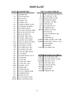
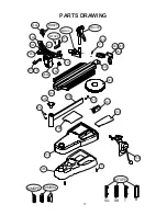
PARTS LIST
PART #
5
6A
8A
9
14
21A
104
105
133
140
141
142
143
144
146A
148L
148R
189
190
192
203
270
282
283
285
286
296A
320
327
335
336
337
MQAC
MDCSC
DESCRIPTION
RUBBER FEET
CAP SCREW- M8
SET SCREW
WASHER- M8
WASHER- M10
FRAME SUPPORT SLIDE
TENSIONER ASSEMBLY
RETAINER SCREW
FRM SUPP SCREW & KNOB
MTNG STAND TOP PLATE
MTNG STAND PAD
SUPPORT ARM- LEFT
SUPPORT ARM- RIGHT
SUPPORT LOCK KNOB
ARM ADJ KNOB & SCREW
SHOULDER V-CLAMP
SHOULDER V-CLAMP
PII LOWER TRAY PAD
PII UPPER TRAY PAD
PII ST PS BASE COVER
TT SCREWS
SUPP MOUNTING PLATE
TURNTABLE
TT END CAP
TT END CAP- RIGHT
TT END CAP- LEFT
SUPPORT POST
BRAKE RING
TURNTABLE PIN
PII ST ALUMINUM BASE
TENSIONER BAR
BRAKE BOX (ST)
TALL QA BASE CLAMP
METAL STRING CLAMP
71
98
109
110
171
196
251
MA
MFSPP
MMSPP
MMSSA
MPSA
MBFC
MDCSC
MGSMC
MPG
MPS
MPXFS
MTC
SGSM
6MM T-HANDLE HEX WRENCH
BOX WRENCH- 10MM
NEEDLE NOSE PLIERS
BENT NOSE PLIERS
DIAGONAL CUTTERS
17MM SOCKET
HEX WRENCH SET
STRINGERS AWL
FRAME SUPP PADS
SQUASH (SQ)
SHORT BADMINTON (SB)
TENNIS (T)
BADMINTON (B)
TENNIS SHLDER SUPP PADS
SHLDER SUPP PADS (L TO R)
RACQUETBALL
BADMINTON
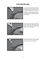
PATHFINDER AWL
BAD FLOATING CLAMP
FIXED BAD STRING CLAMP
MACHINE COVER
STARTING CLAMP
POLISHING STONE
FLOOR STAND
CALIBRATOR
STRINGER’S MAT
TOOLS & ACCESSORIES
OPTIONAL TOOLS & ACCESS