Tools that are needed but not supplied with the high post lamps are: a screw driver, a
wrench and an electrical drill that will be used to anchor the lamp base to the ground.
Solar Lamp Post Location
For optimum light duration throughout the night, it is very important to mount your
solar lamp post in a spot where it will receive the maximum amount of sunlight
throughout the day.
NOTE
: The following steps are for reference only. Consult your local hardware store
for the best installation method for your particular surface.
NOTE
: The solar light must be charged for two sunny days for best results.
Operation Instructions for all models
1.
Unscrew the two knobs in the upper part of the lamp (B) to detach it
from Part A.
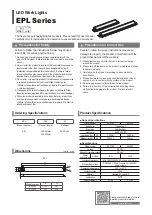
2.
Turn ON the operation switch by choosing your desired brightness
level:
Low (I)
- last longer using dimmer light.
High (II)-
Brighter
light output. (Fig. 1).
3.
Reassemble the upper part of the lamp (B) by screwing the two knobs.
L
M
N
FIG. 1