
© Galvin Engineering Pty Ltd
Version 1, 2 June 2022, Page
3
of
4
Product Installation Guidelines
Version 1, 2
nd
June 2022, Page
3
of 4
INSTALLATION
INSTALLATION COMPLIANCE: Galvin Engineering products must be installed in accordance with these
installation instructions and in accordance with AS/NZS 3500, the PCA and your local regulatory requirements.
Water and/or electrical supply conditions must also comply to the applicable national and/or state standards.
Failing to comply with these provisions shall void the product warranty and may affect the performance of the
product.
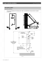
1. Top Flange
Mark the height of the top flange centre point by
measuring vertically 2275mm above the floor. Then
measure approximately 150mm horizontally to the
left or right (depending on the position of the
shower recess) of the centre of the existing supply
fitting. Drill 2 holes Ø8 x 50mm deep, 38mm
horizontally apart to suit the top flange.
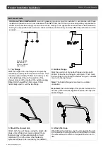
2. Bottom Flange
Mark the position of the
bottom flange’s centre point
mm below the top flange’s centre
point. Then mark
the two holes for mounting the bottom flange in a similar
manner to the top flange.
Note:
The bottom flange is mounted in a vertical
orientation.
Important:
the functionality of this product relies on the
accuracy of the vertical alignment between the top and
bottom flanges.
3. Mount the shower arm
Attach both the wall flanges using the plastic star
plugs and self-tapping screws supplied (these
fasteners may not be appropriate for all wall
materials. If this is the case, other fastening
systems will have to be sourced by the installer).
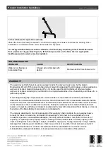
4. Attach the hose
When fitting the inlet hose, lay the arm against the wall
in the
preferred ‘resting’ position, then tighten the hose.
The arm will tend to return to this position when not in
use.
38
DRILL 2 HOLES
Ø8x50 DEEP
2275mm ABOVE
THE FLOOR


