background image


© Galvin Engineering Pty Ltd 


Product Installation Guidelines 

Version 1.1, 30 April 2021, Page 

8

 of 11 


3.  Changing controllers settings 


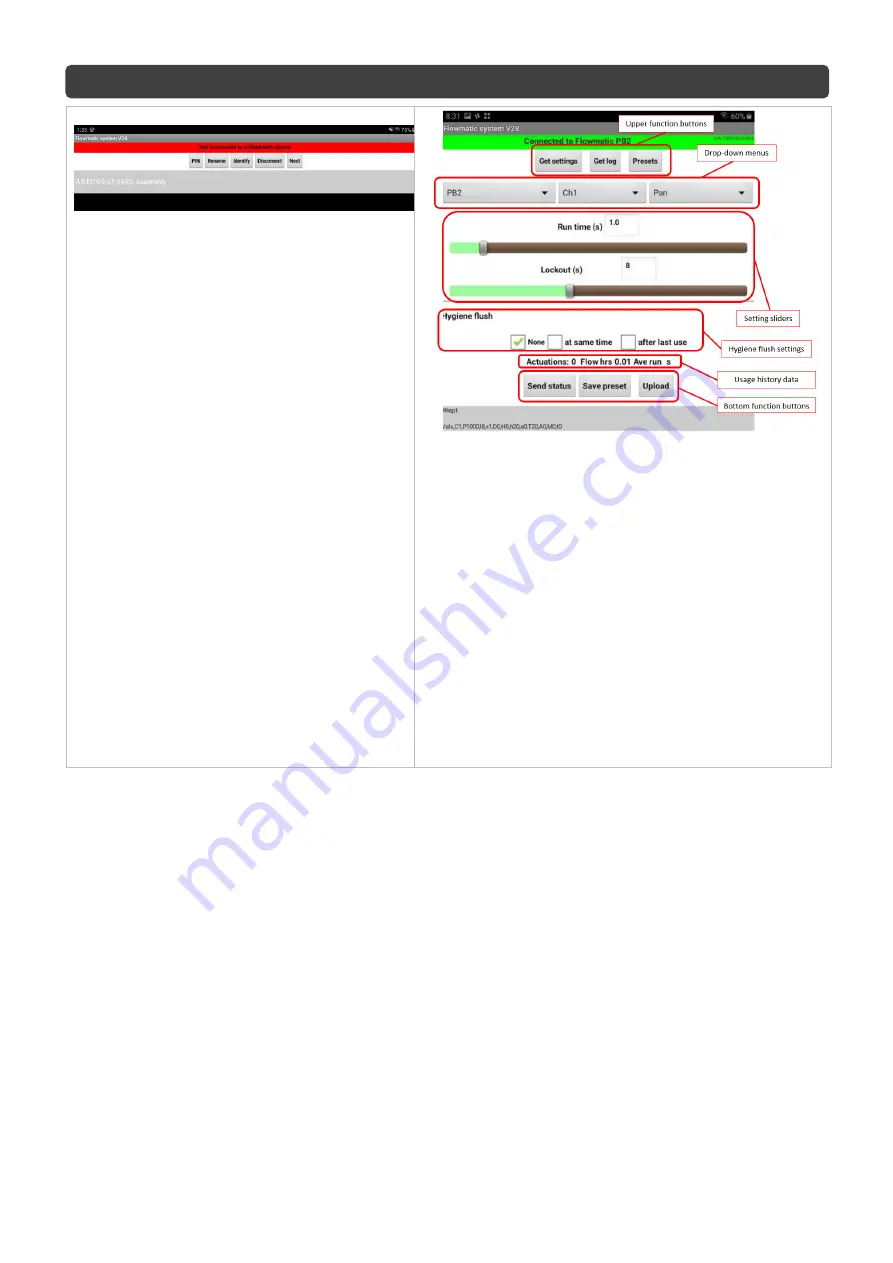
Open the Flowmatic 

system’ app. The 

device will appear on the screen. with Mac 
Address   first and then controller name 
e.g. 

‘AB:EC:69:57:34:02 Flowmatic’.


Select the Flowmatic, this will then update 
the controllers time clock, and then open 
the setting screen by pressing ‘Next’. 

4.  Setting screen overview. 


Upper function buttons

. By pressing the ‘Get settings’ 

button the currently stored parameters in the 
controller’s internal memory will be downloaded to the 
app. The ‘Get log’ button will pop up the log data 
screen. The ‘Presets’ button will list all saved presets. 


Drop-Down menus

. First menu from left is to select 

the type of controller the app is connected to. The 
second menu is to select which 

‘channel’ is going to 

have parameters changed (only for PB2). The third 
menu is to declare what is the controlled feature 
designed for (only for PB2). 


Setting sliders

. Depending on the selected controlled 

feature there will appear one, two or three setting 
sliders. 


Hygiene flush setting

 menu allows to set the time and 

intervals of hygiene flush. 


Bottom function buttons

 are to be used to manage 

the controller internal memory.


Summary of Contents for Flowmatic TZ-FLOWSENC24

Page 1: ...ntinuous reliable delivery of water 1 5mm thick stainless steel face plate with hand activation sensor It is designed to be mounted flush into the wall trough Flowmatic Wall sensor controller is a 24V...

Page 2: ...the outlet sits flat against the wall when installed This is especially important when installing product ranges that have been designed for correctional and health facilities where special attention...

Page 3: ...stalled into a location where a nearby wall or object is reflecting the Infrared light back the unit is effectively blinded and will not operate It is similar to having a torch shone into your eyes No...

Page 4: ...eners to be supplied by installer If more lead is required extension leads are available In this case please contact Galvin Specialised Note For the galvanized box supply and orders please contact Gal...

Page 5: ...supplied by installer If extension leads are required please contact Galvin Specialised Do not force the faceplate to fit onto wall or attempt to disassemble components as this could result in damage...

Page 6: ...sor may require adjustment Please ensure that the sensor is in a position that reflects the actual installation Note The sensor is factory set to medium and will need to be adjusted to suit individual...

Page 7: ...o the Bluetooth settings on your device then scan for devices Generally when scanning the first thing to come up in available devices will be a Mac address that looks like this example AB EC 69 57 34...

Page 8: ...s in the controller s internal memory will be downloaded to the app The Get log button will pop up the log data screen The Presets button will list all saved presets Drop Down menus First menu from le...

Page 9: ...r in front of the sensor Proximity mode If a hand is detected the water turns on for as long as the hand is there up to a certain timeout value set in the Run time section Urinal mode When a user is f...

Page 10: ...ad or power supply lead Check and replace lead controllers Water corroded electrical connections Replace electronic components MAINTENANCE INSTRUCTIONS Sensor The Electronic Sensor is a non serviceabl...

Page 11: ...n the schedule in the manufacturer s warranty During the warranty period Galvin Engineering will replace or repair any defective products manufactured by Galvin Engineering without charge so long as t...

Reviews: