Revision 5
147
August 2021
Section 12
Input / Output (IO) Board Configuration
12.1
IO Board Web GUI
To access the web GUI used to configure the IO board, connect a PC to one of the Ethernet
ports on the analyzer’s control board inside the control cabinet, and ensure that the local
connection status displayed on the
Config
panel
Network
sub panel is showing as
Active
.
The control cabinet door may NOT be opened while the analyzer is energized
UNLESS the area is known to be non-hazardous. Observe all the warning labels
on the analyzer enclosures. To open the control cabinet door while the analyzer
is energized, the purge control box must first be bypassed. Refer to Section 3.3.
Enter the IP address of the analyzer followed by /io.html (i.e. for a locally connected computer
the address would be
) into the address bar of a web browser running
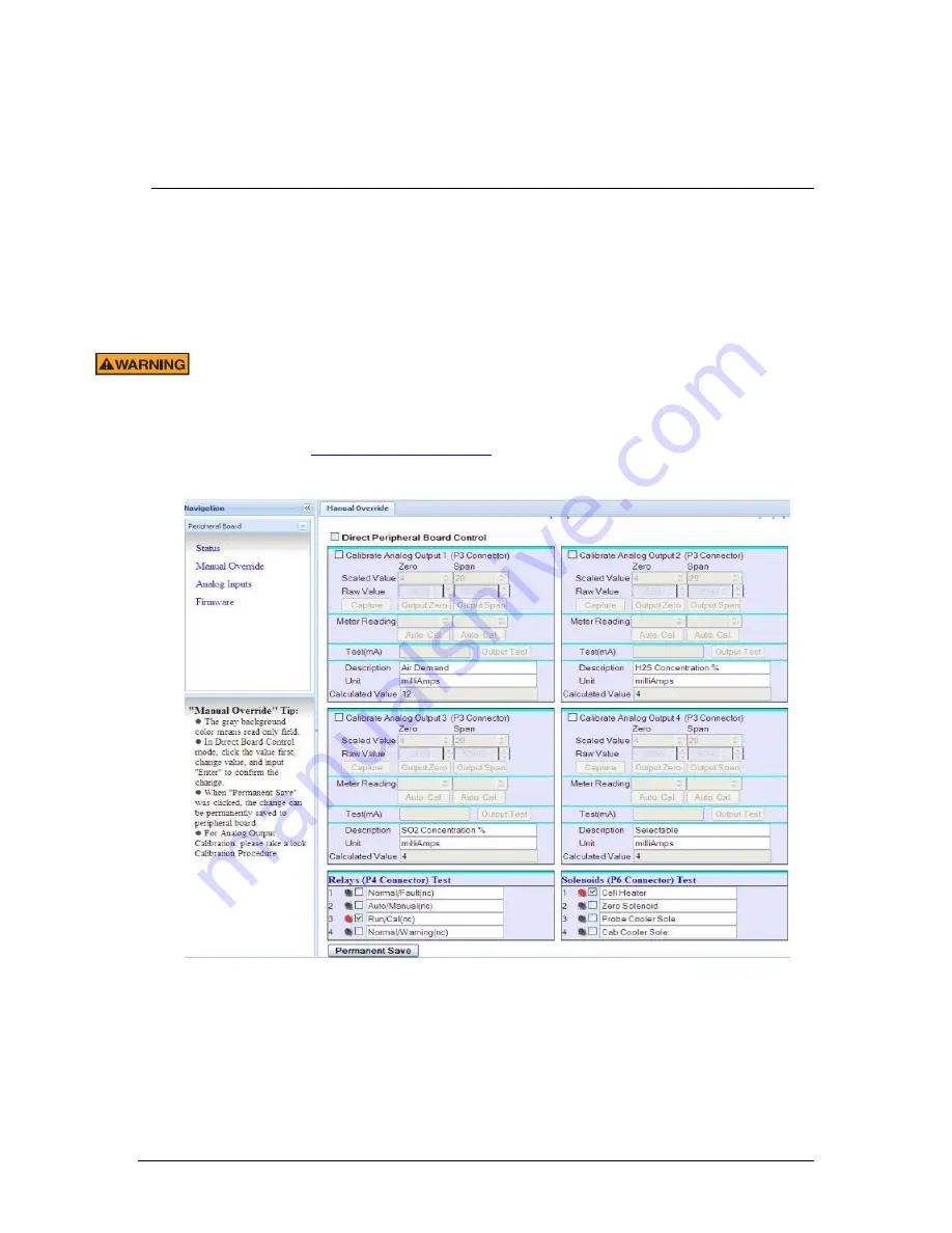
on the connected computer and press Enter. The IO board web GUI is shown in Figure 92.
Figure 92: IO Board web GUI
The
Peripheral Board
menu on the left side of the screen has four pages, as described in Table
37.
Summary of Contents for 943-TGS-CE
Page 137: ...Revision 5 137 August 2021 Figure 84 Oven Cabinet Details...
Page 138: ...Revision 5 138 August 2021 Figure 85 Control Cabinet Door Closed...
Page 139: ...Revision 5 139 August 2021 Figure 86 Control Cabinet Door Removed...
Page 140: ...Revision 5 140 August 2021 Figure 87 Power Steam Air Signals Connection Details...
Page 141: ...Revision 5 141 August 2021 Figure 88 AC Wiring Schematic...
Page 142: ...Revision 5 142 August 2021 Figure 89 DC Signals and Wiring Diagram...
Page 143: ...Revision 5 143 August 2021 Figure 90 Flow Diagram...
Page 144: ...Revision 5 144 August 2021 Figure 91 Control and Oven Cabinets Interconnect Wiring...


