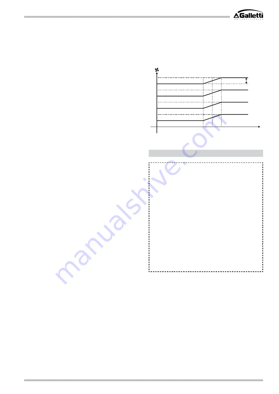
H
50rpm
∆
T
H-
M
M-
L
L-
LL
LL-
1°C
0
1,5°C 2°C
WC66000122 - Rev 03
It is strictly forbidden to reproduce this manual, even partially
3
LATEST GENERATION INVERTER MOTORS
“Moulded” permanent magnet motors controlled by a specifically developed inverter
represents the latest evolution in terms of efficiency (reduced consumption) and
precise fan speed control:
• excellent efficiency (even up to 98%);
• more compact solution;
• considerable reduction in electromagnetic disturbance;
• extended service life, beyond the best, traditional motors.
HUMIDITY SENSORS AND PERCEIVED TEMPERATURE
MANAGEMENT
One of a kind on the market, IWCi incorporates a relative humidity sensor inside its
particularly evolved electronics. The humidity sensor signal is used by the logic by
placing it in relation with the temperature measured by the room air and Humidex sensor,
which measures the perception of the human body considering the combined effects
of temperature and humidity. The implemented algorithm acts on the regulating logic,
modifying the target temperature based on the perceived temperature. The effect is
significant, especially in the summer (cooling mode), i.e. when the environment is very
hot and humid, and therefore needs to be cooled; nonetheless, the algorithm also works
when the cassette is in winter mode, in which case the correction is also imperceptible
because the real temperature and the perceived temperature tend to be the same.
NETWORK MANAGEMENT
The innovative communication system is designed to develop networks such as:
• SACBUS networks with connection to various units with independent adjustment
and control over the operating mode and set points from a single station;
• MODBUS networks with unit management from external supervisor through
Modbus RTU protocol;
• MIXED networks with unit management provided by an external supervisor
through Modbus RTU protocol, and connection to the first and other units
through SACBUS network. Accordingly, the units networked with MODBUS
are controlled by the supervision system, and it is possible to associate other
units to each one of them, which replicate operation through SACBUS network.
IR REMOTE CONTROLLER, WHICH CAN ALSO BE USED AS A
WIRED CONTROLLER DEVICE
There is no distinction between the remote controller and the wired controller
versions: a single object can be used in remote controller or even wall-mounted
controller, by wiring it with a simple twisted pair setting up communication with
the control board on the cassette, and provides the power supply to the control
device itself (no power consumption or need to change batteries)
An infra-red controller device can also be used (with broad transmission range and
insensitive to the interference of fluorescent lights) can be used to control a single
cassette ("one to one" mode) or to control a group of cassettes ("cluster" mode).
If you choose to use an IR remote control, it is possible to configure the individual
remote control devices on 4 different communication frequencies so as to operate
distinctly on 4 different hydronic units.
THE I-FEEL FUNCTION
To provide a greater level of comfort and even more precise control, the user can
choose to base temperature control on a second air probe installed inside the
remote controller.
The correct position of the IR control is therefore essential for excellent operation
of the hydronic cassette.
If it is connected to a network and operating based on perceived temperature, it is
advisable to use the air probe on board the unit.
• Load bearing structure in galvanised steel sheet metal, lined inside and out to
ensure the thermal and acoustic insulation of the unit. The structure houses
the main parts (heat exchange coil, motor ventilation unit and condensation
discharge pump) and is set up for outdoor air intake and the air distribution
in an adjacent room;
• Dynamically and statically balanced backward curved centrifugal fan, fitted
directly to the electric motor, with vane profile designed for extremely silent
and efficient operation, even at a low rpm;
• 230V electric motor, with thermal protection on the coils, 4 speeds to optimise
unit performance in terms of noise and energy;
• High efficiency heat exchange coil with copper tube and aluminium fins,
complete with air relief valves;
• Plastic condensation collection basin, moulded directly inside the structure
of the Styrofoam air directing structure.
2.
CONSTRUCTION FEATURES
SPEED SPLITTING
If you set a ventilation speed, it is possible to start using a "speed splitting" logic.
The logic limits the ventilation speed by a temperature close to the set point.
Accordingly, when the requested temperature is reached, the noise and absorption
of the hydronic cassette drop achieving, at the same time, more precise control.
OPERATING LIMITS
• Plumbing circuit:
- Minimum water inlet temperature: 4°C.
- Maximum water inlet temperature:
main coil: 70°C
secondary coil: 80°C
Note:
For the comfort level (i.e. an even air temperature in the
room), we recommend never exceeding 55°C for the water inlet
to the coil (maximum operating pressure of: 16 bar).
• Ambient air:
- Minimum air inlet temperature: 5°C
- Maximum air inlet temperature: 32°C
Warning: During downtime for installation, if there is a connection
to a fresh air intake or if the room temperature is close to 0°C,
the pipes run the risk of freezing. Set up a drain for the plumbing
circuit.


