background image

Installation and Connection of Galileosky Tracking Device 
version 7 dated from 19.06.2018 


2.


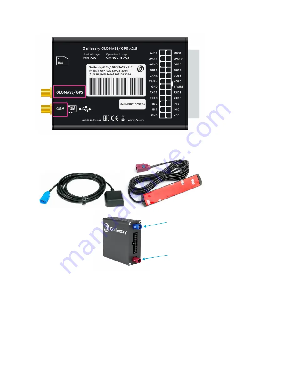
Connection  of  GSM-antennas  and  GLONASS/GPS  antennas  with  Fakra  connector 
(picture 10) is carried out up to clicking position to the correspondent connectors as shown 
in Picture 11.  


Pic. 9 

Connecting 

GLONASS/GPS-

antennas with F type 

connector


Pic. 10 

Antennas with Fakra 

connector


Pic. 11 

Connecting antennas 

with Fakra connector


GSM 

GLONASS/GPS 

Summary of Contents for v 7.0

Page 1: ...Installation and Connection of Galileosky Tracking Device User Manual www galileosky com...

Page 2: ...als 3 Setting of Galileosky Device to Switch on 4 Preparation of the connector a tracking device 4 SIM cards inserting 5 Preparation of antennas 7 Installation of Galileosky components in a vehicle 9...

Page 3: ...cking Device version 7 dated from 19 06 2018 3 Necessary Tools Devices Materials To connect Galileosky tracking devices hereinafter tracking device GPS tracker you should have 1 Electrical tools 2 Mul...

Page 4: ...to be connected and location of main service openings Picture 1 ATTENTION The symbol of tracking device board key is sometimes perceived as a connection strap between RS232 and RS485 contacts Be care...

Page 5: ...install the conductors observe the polarity the red wire is used as a positive conductor and the black wire is used as a negative one SIM cards inserting The order of SIM cards inserting is the follo...

Page 6: ...rt the SIM holder with the card into the tracking device carefully without applying excessive force until locking focusing on the key drawn on the tracking device body Pic 6 ATTENTION Use SIM cards wi...

Page 7: ...ctor 1 The GSM antenna Picture 7 is a passive one and is connected to the GSM antenna plug The GLONASS GPS antenna Picture 8 is an active one It means that it needs a power connection for normal opera...

Page 8: ...nnas and GLONASS GPS antennas with Fakra connector picture 10 is carried out up to clicking position to the correspondent connectors as shown in Picture 11 Pic 9 Connecting GLONASS GPS antennas with F...

Page 9: ...t 2 two direct wires of red and black color from the tracking device to the battery connect the black wire to the negative plug of the battery via 1A fuse connect the red wire to the positive plug of...

Page 10: ...d black color from the tracking device to the nearest places of location of the negative and positive contacts of the vehicle network after disconnection of the ignition key use a multimeter to make s...

Page 11: ...ice placement are shown in Picture 15 of this manual ATTENTION There is an electrical communication between the tracking device body and the negative side of the power supply In order not to damage th...

Page 12: ...e cabin as close to the windscreen as possible Pic 15 or on the vehicle roof as shown in Picture 16 place the GLONASS GPS antenna in the cabin as close to the windscreen as possible Pic 15 on the vehi...

Reviews: