


7
3.
Intended Use
3.1. General
If the equipment is used in a manner not specified by the manufacturer, the
protection provided by the equipment may be impaired.
The product is intended to be installed in a suitable external enclosure.
The device is used in control and instrumentation technology for transfer of
signals such as 20mA and 10V standard signals.
The device has intrinsically safe circuits that are used for operating intrinsically
safe field devices in hazardous areas. Use the device only within the specified
ambient and operating conditions. The device is designed for mounting on a 35
mm DIN rail. The device is intended to be powered by 24V
NEC class 2,
IEC/EN/UL 60950-1 LPS or IEC/EN/UL 601010-1 Limited Energy power source.
Indoor use only or outdoor use when installed in an external enclosure suitable
for outdoor use.
The device may be installed in the non-hazardous area.
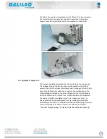
3.2.
Technical Specification
This Input Module intrinsically safe transfers Analog signals from
4-20mA, 0-10V, PT1000, DI. Convert to digital signal, store and send by protocol
Modbus RS485.
Each channel could be settable by a jumper to read any analog signal before
mentioned. The Input Module intrinsically safe prevents the transfer of
unacceptably high energy from the safe area into the hazardous area.
The zener diodes in the Zener Barrier are connected in the reverse direction. The
breakdown voltage of the diodes is not exceeded in normal operation. If this
voltage is exceeded, due to a fault in the safe area, the diodes start to conduct,
causing the fuse to blow. The Zener Barrier has a positive polarity.
3.3 Technical Data
Mechanical Specifications
Mounting
Snap-on 35 mm DIN mounting rail according to EN 60715
Housing Material
Polyamide (PA)
Dimensions
Dimension drawings refer to chapter Dimensions.
Degree of Protection
IP20 according to EN 60529
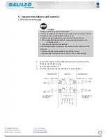
Connection
•
Screw terminals for leads of up to a max. of 2 x 2.5 mm2 (2 x 14 AWG)
• Connection specifications refer to chapter Electrical wiring drawings.
• Observe the tightening torque of the terminal screws. The tightening
torque is 0.5 Nm to 0.6 Nm.
Ambient Temperature
-20 °C to +45 °C (-4 °F to +113 °F)
Storage Temperature
-25 °C to +70 °C (-13 °F to +158 °F)
Relative Humidity
max. 80 % without moisture condensation


