


Installation
Mounting the Controller
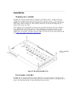
The DMC-41x3 motion controller must be mounted to a flat surface with 4 – #10 pan head screws
through each mounting hole found on the controller base as shown in Figure 15. If the controller is
mounted on a wall, the controller should be mounted so that the bottom of the controller is horizontal
to the floor (as shown in Figure 15). The enclosure must meet or exceed any fire ratings that are
required of the system as a whole.
If the AMP-43xx0 internal amplifiers are being used, it should be determined at this time whether or
not an additional heat sink will be required. This is determined based upon the continuous current
requirements of the system as defined in the “Additional Mounting Consideration when using the
AMP-43xx0” section above. The Motor Sizer tool found on our website can be used to determine this
value
http://www.galilmc.com/learning/motorsizer.php
.
Figure 15: Mounting the DMC-41x3
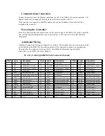
Powering the Controller
The DMC-41x3 is powered via the DC supply connections. All connectors share a common ground.
The DMC-41x3 is grounded through the metal enclosure and should be installed on an unpainted metal
surface. The Earth lugs should be used for additional electrical contact.
Summary of Contents for DMC-41x3
Page 12: ...Figure 16 DMC 41x3 wiring with AMP 43xx0 ...
Page 20: ......


