background image

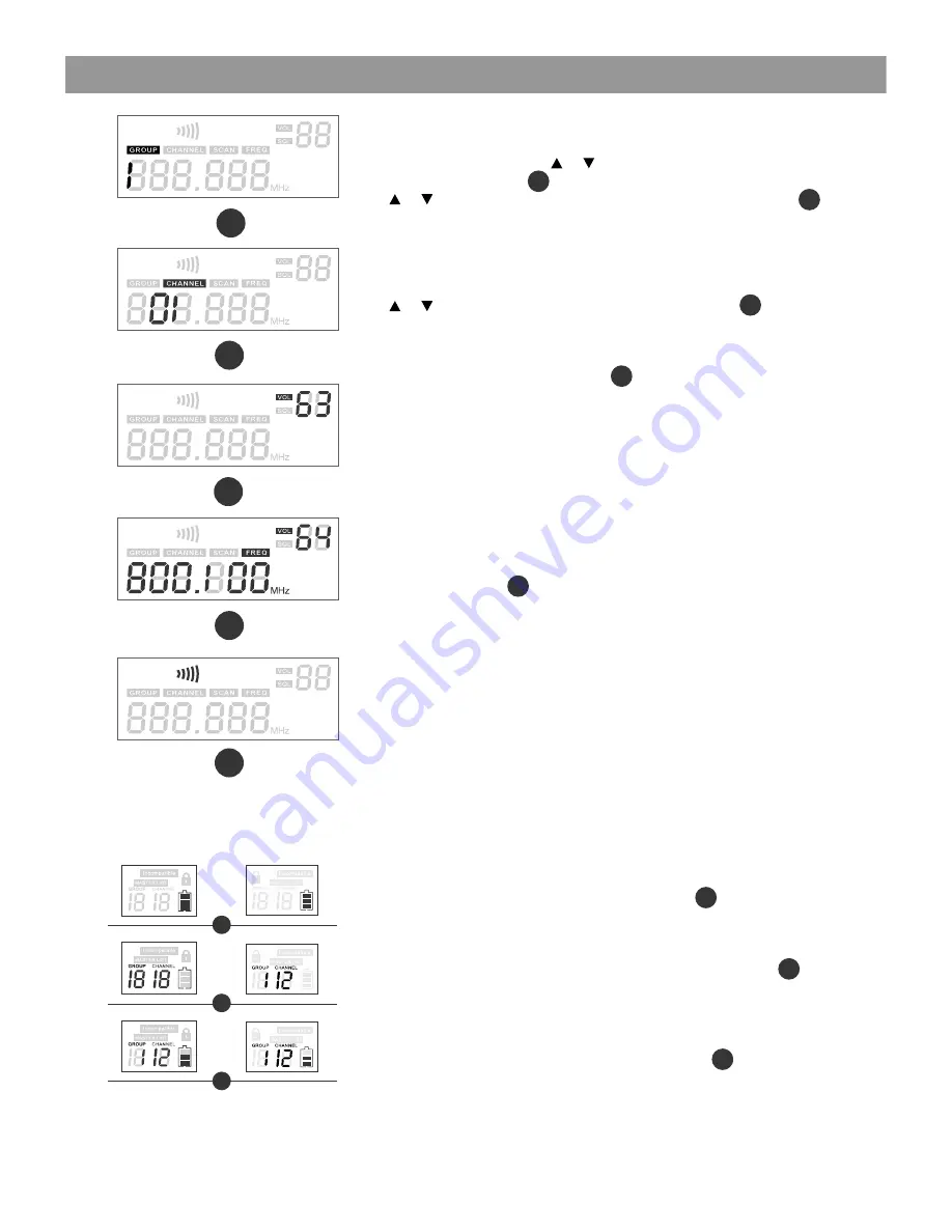
Group and Channel Selection: 

Press and Hold the SET button. The 

Group number will flash. Press    or    to choose the appropriate frequency 
group, as shown on the left 


    ; press (SET) again , (CHANNEL) flashes, 

press    or    to choose the appropriate channel, as shown on the left  


For best results when operating multiple systems, set all systems to a 
single group: then set each system to a unique channel within that group.

Receiver Volume Setting:

The receiver has an electronic volume control. When in the normal display,  
press    or    to control the output volume (64 steps total) as 


  shown at 

left.

Normal Display:

Volume and Frequency, as shown at left       .  
LED columns to the left of the LCD display show RF & AF Levels.

Automatic Transmitter Setup:

Once the desired channel is set on the Receiver, you may allow the 
Transmitter channel to be set automatically. Note: only one Transmitter 
may used with each Receiver. 

Turn on the Transmitter. Position the Transmitter IR window directly in front 
of the Receiver IR window. The IR window of the MBP76 Body Pack is 
located under the battery door while the IR window of the HH64 Handheld 
is located at the bottom end of the mic body. Press the ASC Button on the 
Receiver. The ASC Icon        will flash in the Receiver LCD. The RF Meters 
will light when the synchronisation is complete. The Group and Channel 
number of the Receiver should now be displayed in the Transmitter LCD.
With the HH64 turn on the transmitter after pressing the ASC button. 


Note: 

The Transmitter must be within half a meter distance from

    the Receiver during IR ASC  automatic channel setting. 

HH64 and MBP76 Transmitter Status Display  

Battery Status:

Battery Status Indicators for both the Handheld and Body Pack  
Transmitters feature Four Level Displays as shown in


.


Group and Channel Display:

After completing the ASC, both the Handheld and Body Pack Transmitters 
will display the Group and Channel numbers selected as shown in 


.  


Normal  Display:

Both Handheld and Body Pack Transmitters will display Group and 
Channel numbers as well as Battery Status as shown in 


.

 Handheld 
Transmitter

 Body Pack 
Transmitter

GROUP

CHANNEL

SCAN

FREQ

GROUP

CHANNEL

SCAN

FREQ

GROUP

CHANNEL

SCAN

FREQ

GROUP

CHANNEL

SCAN

FREQ

GROUP

CHANNEL

SCAN

FREQ

GROUP

CHANNEL

SCAN

FREQ

1

2

3

4

5

1

1

2

2

3

3

4

5

Receiver Programming

System Setup

System Setup

1

2

3

5

Summary of Contents for DHT Any Spot

Page 1: ......

Page 2: ...es closely regulate the radio frequencies used in the transmission of wireless information These regulations state which devises can use which frequencies and help to limit the amount of RF radio freq...

Page 3: ......

Page 4: ...etup on Page 8 System Menu Up Button See System Setup on Page 8 System Setup Button See System Setup on Page 8 On Off Switch 8 9 10 11 12 Antenna Jack B 50 ohm XLR Output Jack Output Jack Mute Thresho...

Page 5: ...rt Receivers infrared beam to synchronize frequencies 1 2 3 4 5 6 Functions 1 2 3 4 5 6 Battery Replacement Batteries should be replaced when LCD indicator flashes Unscrew the battery cover as shown b...

Page 6: ...ss or Low Batteries Mute Indicator Constant Red Audio Muted Power Mute Button Push and Hold for Power On Off Push once for Mute On Off IR Window Receives IR signals ASC to synchronize with Receiver Se...

Page 7: ...or while the IR window of the HH64 Handheld is located at the bottom end of the mic body Press the ASC Button on the Receiver The ASC Icon will flash in the Receiver LCD The RF Meters will light when...

Page 8: ...ton and it will set itself to that frequency Do not wait to press the set button as the DHT Receiver will revert back to the original frequency and the process will need to be restarted 10 If the unit...

Page 9: ...k Ears BNC CONNECTOR CABLE For front mounting antenna to rack ears Part AS EXT50 BNC optional Rack Shelf for mounting Two Receivers side by side MRTD P T optional Rack Mounting the Receiver Rack Mount...

Page 10: ...eries in transmitter Distortion or unwanted noise Receiver Indicates RF Remove nearby sources of RF inter ference CD players computers in ear monitor systems etc Distortion level increases gradually S...

Page 11: ...nce 470K ohms Dimensions 3 5 x 2 6 x 1 89mm H x 65mm W x 24mm D Weight 3 0oz 85 g without batteries Power Requirements 2 AA alkaline or rechargeable Batteries batteries Battery Life About 6 hours Rece...

Page 12: ...China Copyright Galaxy Audio 2014 WARRANTY Information can be viewed online at http www galaxyaudio com warranty php Specifications in this manual are subject to change without notice For the most up...

Reviews: