background image

Operation of Bodypack Transmitter AS-TVMBP

A. Battery Installation:

    1. Switch the transmitter off before inserting batteries.

    2. Slide the battery cover off.

    3. Insert 2 disposable batteries (1.5V AA) or 2 rechargeable batteries (1.2V AA).

    4. Observe correct polarity when inserting batteries.

    5. Slide the battery cover back to its original position.
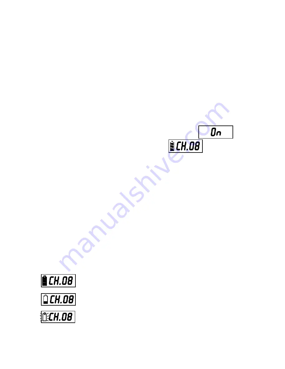
B. Turning unit on:

    1. Switch the power to ON position

    2. 

The RED 

LED will light and  the LCD will display "On". 


Battery status and channel will then appear.

      If no other operation is performed, LCD light will go off automatically in 5 

      seconds.

C. Channel/Frequency Settings:

    1. Press and hold the SET button for approximately 2 seconds until the channel 

        number flashes.

    2. Release the SET button and the current channel will keep flashing 

    3. Press the UP or DOWN buttons to select a different channel. 

    4. When the desired channel is displayed press the SET button again. The

       display will stop flashing and stay on the channel selected.

    5. Press and hold the UP or DOWN buttons to display the frequency associated 

        with the channel number selected.

D. Battery Indications:

    1.                     Batteries fully charged and channel 08 selected.

    
    2.                     One bar displayed indicates low-battery. 

The b

atteries need to 

                            be changed or rechargeable batteries need to be recharged.

    3.                     No bars displayed indicates the batteries are exhausted and  

                            after flashing three times, the power will automatically shut off.

11

12

Description of Functions for Body Pack Transmitter

AS-TVMBP

1. Mini XLR Mic input jack (TA3M)
2. Power switch
3. Mute button
4. Antenna
5. Power light
6. Charging Jack
7. LCD light
8. Set button
9. Channel select button
10. Sensitivity control
11. 3.5mm aux input jack
12. Belt clip
13. Battery compartment
14. Battery cover
 

Summary of Contents for AS-QUAD

Page 1: ......

Page 2: ......

Page 3: ...3 4 Description of Functions for Handheld Microphone Front 6 Description of Functions for Handheld Microphone Rear 7 Operation of Handheld Microphone 8 10 Description of Functions for Body Pack Transm...

Page 4: ...iver and a mix output balanced XLR and unbalanced jacks with a Hi Low level switch The mix output provides a mixed signal from all of the receivers based on the individual volume control settings This...

Page 5: ...evel Indicator 5 Channel Set 6 Channel Selector 7 Module Power Switch Mic Volume 8 Main QUAD Power Switch 9 Antenna B Connector 10 Unbalanced Mix Output 11 Mix Output Level Switch 12 Balanced XLR Mix...

Page 6: ...ng or routing of the Mic Receivers is required Note The Module Ch A Output jack 16 corresponds to the module closest to the Main Power Switch 8 on the front panel and so on down the line 2 Or you may...

Page 7: ...est signal to noise ratio Typically you will want to set the Output Volume controls of the Mic Receiver Modules as high as possible without causing distortion to the Input of the next device and so on...

Page 8: ...esult in the device exceeding the RF exposure requirements and void the user s authority to operate the device This device complies with Part 15 of the FCC Rules Operation is subject to the following...

Page 9: ...er Protects cartridge Front Panel Main Body Contains Wireless Transmitter PCB SET button for channel settings LCD panel Channel and frequency display UP and DOWN buttons For Channel select and Frequen...

Page 10: ...AS TVHH TVHHC Rear Panel Volume Control Three level settings including mute LOW and HI Pushing point Slide the battery cover down by pressing here Battery Cover Lower Housing Remove to slide battery...

Page 11: ...all the lower housing back to the lower part of the microphone B Switch On Steps 1 Press the power switch and hold for about two seconds until the LED turns to RED and on is displayed in the LCD 2 The...

Page 12: ...need to be NiMH AA 1 2V with an amperage of 2100mAH or less as the charging function is limited to batteries of that rating 2 Recharging is best accomplished by using the AS TV8DCC charger 3 Charging...

Page 13: ...al objects 5 Interference and signal Disturbance a Make sure there are no other wireless systems operating on the same frequency in the same area This includes Microphones televisions radio stations e...

Page 14: ...TVMBP 1 Mini XLR Mic input jack TA3M 2 Power switch 3 Mute button 4 Antenna 5 Power light 6 Charging Jack 7 LCD light 8 Set button 9 Channel select button 10 Sensitivity control 11 3 5mm aux input ja...

Page 15: ...tings 1 Press and hold the SET button for approximately 2 seconds until the channel number flashes 2 Release the SET button and the current channel will keep flashing 3 Press the UP or DOWN buttons to...

Page 16: ...tly 2 LCD shows Err when switched on a Switch power OFF repeat steps for turning unit on b If the problem persists call for service 3 No Audio from Transmitter a Check that the Transmitter and Receive...

Page 17: ...sive Heat Don t leave the transmitter or receiver in the hot sun on a radiator or near other sources of high temperature Avoid Rough Handling The transmitter and receiver may be damaged if dropped 14...

Page 18: ...B Adjustable fre quency Switc hing bandwidth Ambient temperature Maximum deviatio n T H D Dynamic range Pre De emphasis Squelch Pre programmed max 96 switchable channels Max 12 MHz 10 C 50 C 50 kHz wi...

Page 19: ...rio us emission Less than 250 nW Display status LCD indi cat or displ ays channe l or freque ncy bat tery condi tion Channel select SET UP DOWN keys AF contro ls Hi Low Mute switch Battery 1 2 V Ni MH...

Page 20: ...ng Less than 250 nW LCD indicator displ ays channel or frequ ency battery life SET UP DOWN keys Mute switch Hi Mid Lo w switch Mic in Aux in 1 2 V Ni MH 1300 mAh 2 AA type rech arge able battery 1 5V...

Page 21: ..._______________________ _________________________________ _________________________________ _________________________________ __________________________________ Name________________________Phone______...

Page 22: ...PLACE STAMP HERE GALAXY AUDIO P O BOX 16285 WICHITA KS 67216 0285...

Page 23: ...XY AUDIO product which has been altered or on which the serial number has been effaced or removed If your unit requires service it must be returned shipping charges prepaid to GALAXY AUDIO in the Unit...

Page 24: ...V09222008...

Reviews: