background image

GAR AC/DC 180. Instructions Manual.

17

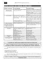
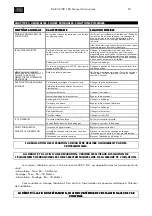
CAPITULO 5. ANOMALIAS. CAUSAS PROBABLES. SOLUCIONES POSIBLES.

SYMPTOM. ANOMALY

SYMPTOM. ANOMALY

SYMPTOM. ANOMALY

SYMPTOM. ANOMALY

PROBABLE CAUSE

PROBABLE CAUSE

PROBABLE CAUSE

PROBABLE CAUSE

POSSIBLE SOLUTION

POSSIBLE SOLUTION

POSSIBLE SOLUTION

POSSIBLE SOLUTION

GENERAL PROBLEM

NOTHING WORKS.

The machine has no voltage in one or all its vital

elements.

Make sure there is voltage at the entry to the machine;

if not the intake must be changed or the supply hose

repaired.  It is advisable to see if any magnetothermal

has "blown".

The machine panels must be removed testing the

logical points of the electrical diagram.

LIMITER TRIPS

Magnetothermal switch has low gauge for the

case.  There may be a shortcircuit which is what

causes the limiter to trip.

Change the magnetothermal for another larger gauge

one. It is important for the magnetothermal switch to

have a characteristic slow type curve.  In the event that

the electrical installation has limited power the welding

work must be tested at lower current levels.

Coil burnt (Primary)

Change coil.

Connection is made to 220 V when the power

supply was 380 V.

Change position of on/off switch. Place the safety

switch into its correct position.

ALTHOUGH THE MACHINE IS

CONNECTED AND WITH LIGHT

K ON, THE MACHINE DOES NOT

CARRY OUT THE WELDING

OPERATION

Defect in the electrical wiring diagram.

Test internal connections. Test switch points, voltage at

transformer ouput (40V approximately)

IT WORKS AT LOW INTENSITY

The electrical supply is not correct.

Change the supply intake.

Supply cables broken or badly connected.

Repair connection.

Switch broken

Change switch.

Loose coil or connection.

Repair connection.

Coil burnt (Primary)

Change coil.

One phase is missing

Repair electrical connection

Secondary coil burnt

Change coil

Diodes deteriorated

Change rectifier

Blocks broken

Change blocks.

THERE ARE NOISES

Metal shell loose

Check and screw shell

Spirals loose in one of the coils

Change or varnish the coil

THE ELECTRODE BURNS IN THE

T.I.G. WELDING

No protection gas

Set at a suitable flow volume.

Excessive welding intensity for a certain electrode Decrease welding current or change electrode for

another one with greater diameter

Use of inverse polarity

Place the electrode at negative pole

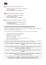
ANY WORK ON THE EQUIPMENT MUST BE CARRIED OUT BY SPECIALISED PERSONNEL

BOTH AT THE BEGINNING AND END OF A REPAIR CHECK THE EQUIPMENT INSULATION LEVELS.

DISCONNECT THE ELECTRONIC PLATES WHEN MEASURING THE INSULATION.

The insulation measuring instrument will have 500 V D.C. and will be applied at the following points of the

circuit:

- Supply-Earth: RA>50 Mohms
- Welding-Earth: Ra>50 Mohms
- Supply-Welding: Ra>50 Mohms

In the event that lack of insulation is observed it is likely that this is due to the accumulation of metal dust on

the inside of the equipment.

BOTH AT THE BEGINNING AND END OF A REPAIR, BLOW THE INSIDE OF THE EQUIPMENT WITH

BOTH AT THE BEGINNING AND END OF A REPAIR, BLOW THE INSIDE OF THE EQUIPMENT WITH

BOTH AT THE BEGINNING AND END OF A REPAIR, BLOW THE INSIDE OF THE EQUIPMENT WITH

BOTH AT THE BEGINNING AND END OF A REPAIR, BLOW THE INSIDE OF THE EQUIPMENT WITH

COMPRESSED AIR.

COMPRESSED AIR.

COMPRESSED AIR.

COMPRESSED AIR.

Summary of Contents for Gar AC/DC 180

Page 1: ...ESIONALES EN BENEFICIO DE SU TRABAJO LEA ATENTAMENTE ESTE MANUAL GB THIS EQUIPMENT MUST BE USED BY PROFESSIONALS TO HELP YOU IN YOUR WORK READ THIS MANUAL CAREFULLY F CET EQUIPEMENT DOIT ETRE UTILISE...

Page 2: ...NSTALLATION Page 12 CHAPTER 3 START UP OPERATION AND ADJUSTMENTS Page 14 CHAPTER 4 MAINTENANCE OPERATIONS RECOMMENDATIONS Page 16 CHAPTER 5 ANOMALIES PROBABLE CAUSES POSSIBLE SOLUTIONS Page 17 CHAPTER...

Page 3: ...nsiones generales de los equipos GAR AC DC Fig 1 Dimensiones generales de los equipos GAR AC DC Fig 1 Dimensiones generales de los equipos GAR AC DC Fig 1 Dimensiones generales de los equipos GAR AC D...

Page 4: ...endo a las normas en vigor El emplazamiento deber cumplir los siguientes requisitos Lugar Seco y ventilado alejado suficientemente del puesto de soldadura con el fin de evitar que el polvo y poluci n...

Page 5: ...l nea el ctrica de fuerza podemos conectar el equipo de forma BIFASICA a 380 V Esta conexi n tiene la ventaja de aprovechar la capacidad de absorci n de potencia que conllevan las l neas el ctricas de...

Page 6: ...ectrodo revestido Electrodo revestido Electrodo revestido 1 Situe la pinza y masa de soldadura en los conectores E del frontal del aparato vease Fig 5 2 Regule la corriente de soldeo mediante el volan...

Page 7: ...pinza y masa en los conectores F del equipo Figura 5 A este respecto es muy importante que tenga en cuenta la polaridad de conexi n Electrodo a negativo DC Polaridad directa Electrodo a negativo DC Po...

Page 8: ...do una colocaci n a corta distancia Mantener la m quina limpia y seca es fundamental Debe soplarse el interior con la frecuencia que sea necesaria Debemos evitar cualquier anomal a o deterioro por la...

Page 9: ...r tensi n en entrada del rectificador 40V aproximadamente LA SOLDADURA ES A BAJA No existe alimentaci n el ctrica correcta Cambiar la toma de alimentaci n INTENSIDAD Cables de alimentaci n rotos o mal...

Page 10: ...e existencia de grasas y disolventes dado que estas pueden descomponerse en el proceso de soldadura desprendiendo un humo que puede ser muy t xico Esto mismo puede suceder con aquellos materiales que...

Page 11: ...C DC Fig 1 General dimensions of the Gar AC DC equipment General Aspect equipment General Aspect equipment General Aspect equipment General Aspect The Technical data of the equipment are given on a ch...

Page 12: ...t by specialised personnel according to the standards in force The location must meet the following requirements Place Dry and ventilated far enough away from the welding area in order to prevent the...

Page 13: ...on B Connection to lighting line B Connection to lighting line B Connection to lighting line B Connection to lighting line A Connection to the power line Taking two wires from the electrical power lin...

Page 14: ...current with wheel C to the desired welding intensity value The adjustment value is given on part F4 of the dial see figure 7 3 Apply the on off switch A depending on the supply voltage The adjustmen...

Page 15: ...the electrodes with rutlile type coating Connect the clip to negative and the ground to positive Electrode de positive DC Inverse polarity As a general rule this is the polarity of the basic or speci...

Page 16: ...on As an essential measure the equipment must be kept separate from the welding place placing it some distance away Keeping the machine clean and dry is essential The inside must be blown as required...

Page 17: ...supply is not correct Change the supply intake Supply cables broken or badly connected Repair connection Switch broken Change switch Loose coil or connection Repair connection Coil burnt Primary Chang...

Page 18: ...se or solvents as these may decompose during the welding process giving off fumes which could be very toxic This can also occur with those materials which have some kind of surface coating zinc plated...

Page 19: ...ts GAR Fig 1 Dimensions g n rales des quipements GAR AC DC Aspect G n ral AC DC Aspect G n ral AC DC Aspect G n ral AC DC Aspect G n ral Les donn es techniques de l quipement sont recueillies sur une...

Page 20: ...p cialis es et en respectant les normes en vigueur L emplacement devra remplir les crit res suivants Lieu Sec et a r Suffisamment loign du poste de soudage afin d viter que la poussi re et la pollutio...

Page 21: ...Phase I Neutral Fiche de branchement Prise de Terre B Branchement ligne de force B Branchement ligne de force B Branchement ligne de force B Branchement ligne de force A Branchement la ligne de force...

Page 22: ...nrob e lectrode enrob e lectrode enrob e lectrode enrob e 1 Situer la pince et la masse de soudage dans les connecteurs E du frontal de l appareil voir Fig 5 2 R gler le courant de soudage au moyen du...

Page 23: ...ectrodes sp ciales il procure une grande stabilit de l arc le processus de soudage est doux et efficace Utiliser ce mode de travail chaque fois que le processus n exige pas un facteur de marche sup ri...

Page 24: ...machine sera ainsi d branch e L intervention sur la machine pour l entretien et la r paration doit tre r alis e par des professionnels SOUFFLER R GULI REMENT AVEC DE L AIR COMPRIM L INT RIEUR DE LA M...

Page 25: ...rrecte Changer la prise d alimentation INTENSIT C bles d alimentation ab m s ou mauvais branchement R parer le branchement Interrupteur d t rior Changer l interrupteur Mauvais bobinage ou branchement...

Page 26: ...nts de la pi ce de travail tant donn qu ils peuvent se d composer lors du processus de soudage d gageant une fum e qui peut tre tr s toxique Il en est de m me avec des mat riaux qui composent certains...

Page 27: ...ones de este manual y las siguientes recomendaciones Antes de instalar el material de soldadura debe tener en cuenta la presencia en los alrededores de Cables de potencia control se alizaci n y tel fo...

Page 28: ...mas EJEMPLO EJEMPLO EJEMPLO EJEMPLO GAR AC DC 180 Ref 511 00 000 220 380V 50Hz 1Ud RECTIFICADOR Ref 511 06 005 GENERAL GUARANTEE CONDITIONS GALA GAR S A guarantees correct operation against all manufa...

Page 29: ...essoires inad quats service non autoris ou modification du produit non r alis par GALA GAR S A La d cision de r parer remplacer des pi ces ou fournir un nouvel appareil appartiendra GALA GAR S A Toute...

Page 30: ...ernet http www galagar com DELEGACIONES Pol gono Sta Ana C Joaqu n Sorolla 61 Tel 91 499 04 82 Fax 91 499 04 83 28529 RIVAS VACIAMADRID MADRID Avenida de los Chopos 59 B 2 A Tel 94 430 60 89 Fax 430 6...

Reviews: