GS2200M Starter Kit Board Hardware User Guide
GS2200M Starter Kit Board Pinouts
46
GS2K-SKB-HW-UG-001278, Release 1.0
B.1.5 GS2200M SKB Arduino Connector Pinouts
The SKB may be configured as host or a shield. Each field shows the label with the GS2K
signal listed in parenthesis. The UART port can be configured to route to UART0 or
UART1 of the GS2000 via header J18. +5V can optionally be supplied from the 5.0V
regulator to power to shields. VIN can also be optionally supplied with 5V directly from
the USB port. The SPI port can be configured for master or slave mode via header J20. In
shield mode, +5V can be used as the power source by setting jumper J19 appropriately.
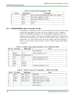
gives the pin
assignments.
Table 16 I2C Header Pin Assignments - SKB
Pin No.
Signal Name
Description
1
ALM_N
Extra pin for interrupt/alarm signal (RTC_IO_2, jumper)
2
SCL
Serial Clock (GPIO9/I2C_CLK)
3
SDA
Serial Data (GPIO8/I2C_DATA)
4
GND
Ground
5
VSN
VCC
Table 17 Arduino Connector Pin Assignments - Power Header (J3) SKB
Pin No.
Pin Name
SKB Signal
Notes
1
Not Connected
2
IOREF
VSN
Jumper Enabled (J10 7-8)
3
GPIO28/RSTn GPIO28/RESET_n
4
VSN
VSN
Jumper Enabled (J10 9-10)
5
+5V
5V
Jumper Enabled (J10 11-12)
6
GND
Ground
7
GND
Ground
8
VIN
VUSB0
Jumper Enabled (J10 13-14)
Table 18 Arduino Connector Pin Assignments - A/D Header (J4) SKB
Pin No.
Pin Name
SKB Signal
Notes
1
ADC0
ADC_SAR_0
SAR ADC
2
PMEAS
PWR_MEAS-A
Jumper Enabled (J10 5-6)
3
SD0P
ADC_SD_0P
Sigma Delta Positive Terminal
4
SD0N
ADC_SD_0N
Sigma Delta Negative Terminal
5
Not Connected
6
Not Connected


