Pin-out and Signal Description
GS2011M Low Power WiFi Module Data Sheet
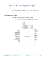
GS2011Mxx Device Pin-out
44
Confidential
Preliminary
GS2011M-DS-001211, Release 0.9
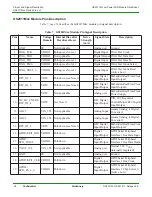
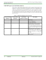
GS2011M Program and Code Restore Options
describes the options available for device program mode and code restore
capabilities. The respective GPIO pins are sampled at reset by device and depending on the
values seen on these pins goes into the appropriate mode. Code for the GS2011M resides
on the internal flash of the module and up to two back-up copies could be stored in flash.
If a software designer wants to restore the execution code to one of the backup copy, it can
be accomplished by asserting the appropriate GPIO pins as shown in the table below during
power up or reset.
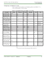
Table 9 GS2011M Pin Program and Code Restore
Program Mode
(GPIO 27)
Program Select
(GPIO 25)
Code Restore
(GPIO 21 or GPIO 1)
Description
0
X
0
Normal boot
0
0
1
Factory Code Restore
0
1
1
Previous Code Restore
1
0
X
Program Mode for code load using
UART 0 interface @115.2Kbaud or
using SPI0 on SDIO pins (Default Mode
if you don’t pull the Program Select pin
high)
1
1
X
Program Mode for code load using
UART 0 interface @921.6Kbaud or SPI0
interface on GPIO15-18 or using SDIO
interface.
Note: These options are targeted for a
future revision.

