GAI-Tronics RigCom 400-001 Manual Download Page 22

Pub. 42004-376D 

Models 400-001 and 400-002NS RigCom Stations 

Page 20 of 20 

P:\Standard IOMs - Current Release\42004 Instr. Manuals\42004-376D.docx 
09/18 


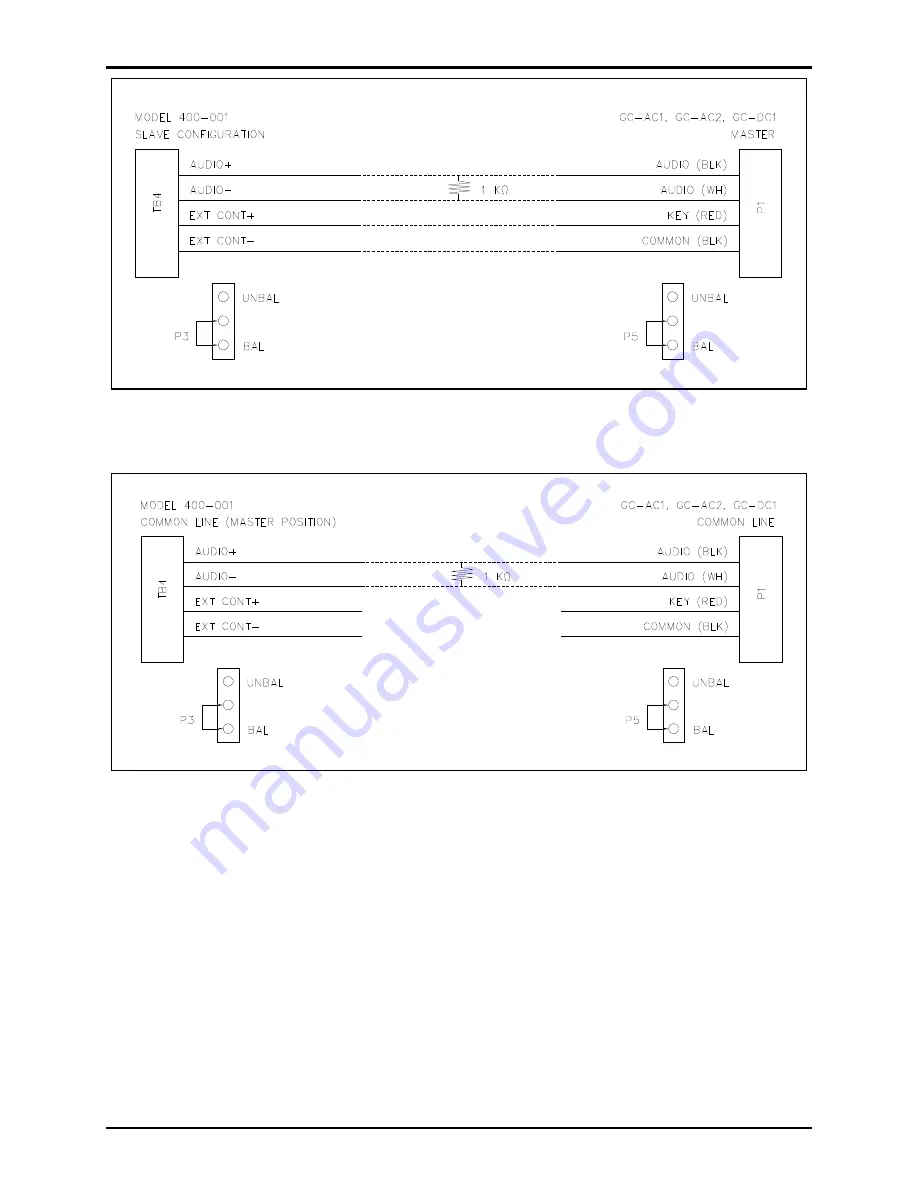
Figure 17.  Master/Slave Balanced Configuration with Model 400-001 as Slave 


Figure 18.  Balanced Common Line Configuration 

Summary of Contents for RigCom 400-001

Page 1: ...001 Only 3 Mounting 4 Hardware Configuration 5 External 5 Internal 5 Wiring 6 Station Wiring 6 System Line Balance 7 System Wiring 9 Field Installation Interface 9 TB1 Speaker Terminal Block 9 TB2 AC...

Page 2: ...1212 Fax 610 796 5954 VISIT WWW GAI TRONICS COM FOR PRODUCT LITERATURE AND MANUALS Speaker Model 400 001 Only 15 Station 15 Environmental 15 Approvals 16 Appendix A InterfacingaModel400 001RigComStat...

Page 3: ...lk or master slave communication system for the following hazardous locations Model 400 001 Class I Div 1 Groups C and D Model 400 002NS Class I Div 1 Groups B C and D when installed in accordance wit...

Page 4: ...eries of GAI Tronics equipment Important Safety Instructions 1 Read follow and retain instructions All safety and operating instructions should be read and followed before operating the unit Retain in...

Page 5: ...and washers or washer head bolts WARNING Insure proper grounding to protective earthing Do not disconnect equipment while energized Inspect and clean the machined flange flame joint surfaces of both...

Page 6: ...ght of the aluminum enclosure See the Specifications section for the weights and dimensions of the unit The enclosure must be securely fastened with 7 16 inch diameter steel mounting bolts located on...

Page 7: ...LASS I DIV I GROUPS C D WARNING EXPLOSION HAZARD DO NOT DISCONNECT EQUIPMENT UNLESS TO REDUCE THE RISK OF IGNITION OF HAZARDOUS ATMOSPHERES CONDUIT SEALS MUST BE INSTALLED WITHIN 18 INCHES OF ENCLOSUR...

Page 8: ...the wires to the terminal blocks located on the PCBA within the enclosure see Figure 4 for connection points and descriptions 5 If using the 10438 001 Auxiliary Microphone Assembly Connect the assemb...

Page 9: ...or assembly is made for easy installation into the customer supplied junction box NOTE Only one line balance resistor assembly is needed per system The resistor assembly should be installed in a junct...

Page 10: ...76D Models 400 001 and 400 002NS RigCom Stations Page 8 of 20 P Standard IOMs Current Release 42004 Instr Manuals 42004 376D docx 09 18 Figure 6 Master Slave System cable wiring greater than 4000 feet...

Page 11: ...in talk mode the signal level reduces by half see Figure 7 for systems with more than ten stations to determine the maximum line distance Figure 7 Number of Stations vs Line Length Field Installation...

Page 12: ...ower supply negative terminal No connection when external dc power supply is not used TB4 AudioandLow VoltageControl TerminalBlock The following table lists the connections for the low voltage control...

Page 13: ...SW1 allows configuration of the unit as a master or slave unit The unit is configured as a master if the switch is in the MASTER position The unit is configured as a slave if the switch is in the SLAV...

Page 14: ...s The push to talk switch must be held down as long as the operator talks Releasing the switch deactivates the microphone and returns the unit to listen mode Figure 8 Common Talk Wiring Detail Master...

Page 15: ...ance section unless you are qualified to do so Regular inspection and a good preventive maintenance program will increase the reliability of your GAI Tronics station The GAI Tronics Field Service Depa...

Page 16: ...th Install and tighten all cover bolts to 17 ft lb 23 N m Make certain no cover bolts are omitted Use only the bolts supplied with the enclosure Troubleshooting Problem Solution Any problem with stati...

Page 17: ...output Gain Listen mode 17 dB Gain Talk mode speaker as the microphone 42 dB Gain Talk mode auxiliary microphone 48 dB Speaker Model 400 001 Only Rating 30 W maximum Impedance 16 Frequency response 4...

Page 18: ...400 001 RigCom Station is designed to operate as a field replacement or system addition to the MS39xx RigCom Stations The MS39xx uses an unbalanced system for communication and uses the negative of th...

Page 19: ...Model 400 001 Stations are designed to operate either in balanced or unbalanced systems An unbalanced system for communication uses the negative of the audio pair as the ground reference for the contr...

Page 20: ...tions Page 18 of 20 P Standard IOMs Current Release 42004 Instr Manuals 42004 376D docx 09 18 Figure 13 Master Slave Unbalanced Configuration with the Model 400 001 as Master Figure 14 Master Slave Un...

Page 21: ...00 002NS RigCom Stations Page 19 of 20 P Standard IOMs Current Release 42004 Instr Manuals 42004 376D docx 09 18 Figure 15 Unbalanced Common Line Configuration Figure 16 Master Slave Balanced Configur...

Page 22: ...400 002NS RigCom Stations Page 20 of 20 P Standard IOMs Current Release 42004 Instr Manuals 42004 376D docx 09 18 Figure 17 Master Slave Balanced Configuration with Model 400 001 as Slave Figure 18 B...

Page 23: ...of the Contractor s personnel from the work site Re performance of services shall be Buyer s sole and exclusive remedy and in no event shall GAI Tronics warranty obligations with respect to services e...

Reviews: