background image

Pub.  42004-178D 

Model 263 Isolation Barrier Unit (IBU) 

Page: 4 of 13 

\\s_eng\gtcproddocs\standard ioms - current release\42004 instr. manuals\42004-178d.doc 
03/06 

System Setup 

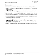
GAI-Tronics recommends taking the following steps to ensure a safe and trouble-free installation: 

1. Install the Model 263 Isolation Barrier Unit (IBU) and wire it completely, except for the hazardous

area signal wires.

WARNING

 The unit must be wired in accordance with Pub. 42004-380, Control 

Drawing 73242, to ensure intrinsic safety. 

2. Next, temporarily connect the I.S. telephone to the IBU with a short pair of conductors, and operate

the unit by making a test phone call.  If any problems are detected, see the Troubleshooting section.

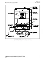
3. Call the I.S. telephone from another telephone, and adjust the 

RING PITCH

 (located on the IBU) to

the desired pitch.  See Figure 2 for location.

4. Disconnect the I.S. telephone and install it in the intended permanent location.

WARNING

 The unit must be wired in accordance with Pub. 42004-380, Control 

Drawing 73242, to ensure intrinsic safety.


5. Make a call from the I.S. telephone.  If any problems are detected, see the Troubleshooting section.

Summary of Contents for 263

Page 1: ...ty General Information GAI Tronics Corporation offers intrinsically safe I S telephones and isolation barrier units IBU which conform to all pertinent requirements in the USA and Canada For convenience a telephone and an IBU can be purchased together under a single model number Model 261 001 for indoor use and Model 271 001 for outdoors However for rack mount configurations or special applications...

Page 2: ...k is specifically designed for wet locations NEVER touch uninsulated telephone wires or terminals unless the telephone line has been disconnected at the network interface USE CAUTION when installing or modifying telephone lines Install UL Listed telephone line suppressor customer supplied on the telephone line Use silicone sealant or equivalent around and inside all conduit entries Installation of...

Page 3: ...e cable capacitance level was still within acceptable bounds Cable types with less capacitance have been specified to allow connection distances over one mile For example GAI Tronics Model 60059 001 and 60021 301 cables allow connection distances of up to 1 5 miles Shielded Cable Where multiple I S telephone wires are routed together shielded cable should be used The use of shielded cable prevents...

Page 4: ...73242 to ensure intrinsic safety 2 Next temporarily connect the I S telephone to the IBU with a short pair of conductors and operate the unit by making a test phone call If any problems are detected see the Troubleshooting section 3 Call the I S telephone from another telephone and adjust the RING PITCH located on the IBU to the desired pitch See Figure 2 for location 4 Disconnect the I S telephon...

Page 5: ...ub 42004 178D Model 263 Isolation Barrier Unit IBU Page 5 of 13 s_eng gtcproddocs standard ioms current release 42004 instr manuals 42004 178d doc 03 06 Figure 2 Rear of IBU enclosure with cover removed ...

Page 6: ...closure Install the rear enclosure to a wall of an appropriate surface through the supplied mounting holes 4 Refer to Pub 42004 380 Control Drawing 73242 for wiring details NOTE Telephone system wire must be connected to the Isolation Barrier Unit only and not directly to the I S telephone Battery backup connection is not required for operation of the Model 262 001 and 272 001 I S Phones If batter...

Page 7: ...ge 7 of 13 s_eng gtcproddocs standard ioms current release 42004 instr manuals 42004 178d doc 03 06 Figure 3 Model 263 Isolation Barrier Unit dimensions Operation The Model 263 Isolation Barrier Unit requires no operator intervention for routine functions ...

Page 8: ... Non EquipmentRelated Problems Problem Solution The I S phone is inactive with no lights on the IBU when the phone is off hook 1 Check the ac power to the Model 263 IBU 2 Check the ac fuse F4 at the Model 263 IBU 3 Ensure there is no wiring open at the I S phone 1 If the I S phone has a wiring short the IBU lights will be lit in the following pattern O On P Off ISLOOP O LOCK P HOOK P TELCO P 2 If ...

Page 9: ...short in the connecting cable Cannot dial out but can hear touch tones when pressed 1 Check the Model 263 IBU 2 There is no TELCO connection or it is faulty I S phone appears inactive 1 Check the I S telephone panel 2 Check the ac fuse F4 at the Model 263 IBU 3 Ensure there is no wiring open in the connecting cable or at the I S telephone CAUTION Any field repairs on the intrinsically safe design ...

Page 10: ... lightning strike To ensure safe operation protective elements should be replaced frequently and checked for proper connection and grounding Gas discharge types are by far the most robust cost effective means of protection The registered I S equipment meets all isolation and safety requirements of FCC Part 68 DOC CS 03 UL 913 and CSA C22 2 No 157 However lightning strikes are not predictable or co...

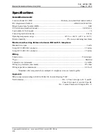
Page 11: ...to 140 F 40 C to 60 C Relative humidity 95 non condensing maximum Maximum safe wiring distance between IBU and I S telephone Standard wire types 1 mile Using GTC 60059 001 conductor 1 5 miles Using GTC 60021 301 conductor 1 5 miles Wiring Construction Twisted pair Type Shielded Conductor size minimum 24 AWG Wiring loop resistance maximum 275 ohms Wiring capacitance maximum 0 316 uF Shielded cable ...

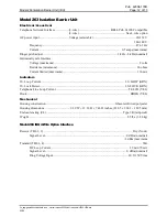
Page 12: ... Intrinsically safe Interface Voltage maximum 8 volts Resistance minimum 66 ohms Current limited maximum 136 mA Indicators I S Loop Current I S LOOP GRN I S Lock Detect I S LOCK GRN Telephone Line Loop Current TELCO YEL Hook HOOK YEL Mechanical Housing construction Glass reinforced polyester Housing dimensions 9 39 W 13 16 H 7 46 D inches 238 5 334 3 189 5 mm Enclosure rating UL Type 3R rainproof ...

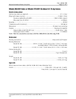
Page 13: ...ompatible Output 0 dBm IBU TELCO Line 105 dB SPL 1 kHz Audio signal loss 18 AWG 1 3 dB mile NOTE Must be connected in accordance with Pub 42004 380 Control Drawing 73242 Mechanical Housing construction Glass reinforced Polyester Housing dimensions Model 262 001 8 02 W 9 52 H 6 86 D inches 203 7 241 8 174 2 mm including handset 3 86 D 98 mm without handset Model 272 001 9 39 W 13 16 H 7 46 D inches...

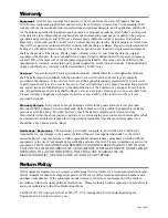
Page 14: ... of the Contractor s personnel from the work site Re performance of services shall be Buyer s sole and exclusive remedy and in no event shall GAI Tronics warranty obligations with respect to services exceed 100 of the total cost of the services provided hereunder Warranty Periods Every claim by Buyer alleging a defect in the goods and or services provided hereunder shall be deemed waived unless su...

Reviews: