Pub.
42004-339F
M
ODEL
226-002,
341-001,
AND
351-001
D
IV
.
2
I
NDUSTRIAL
T
ELEPHONES
P
AGE
9 of 14
e:\standard ioms - current release\42004 instr. manuals\42004-339f.doc 07/14
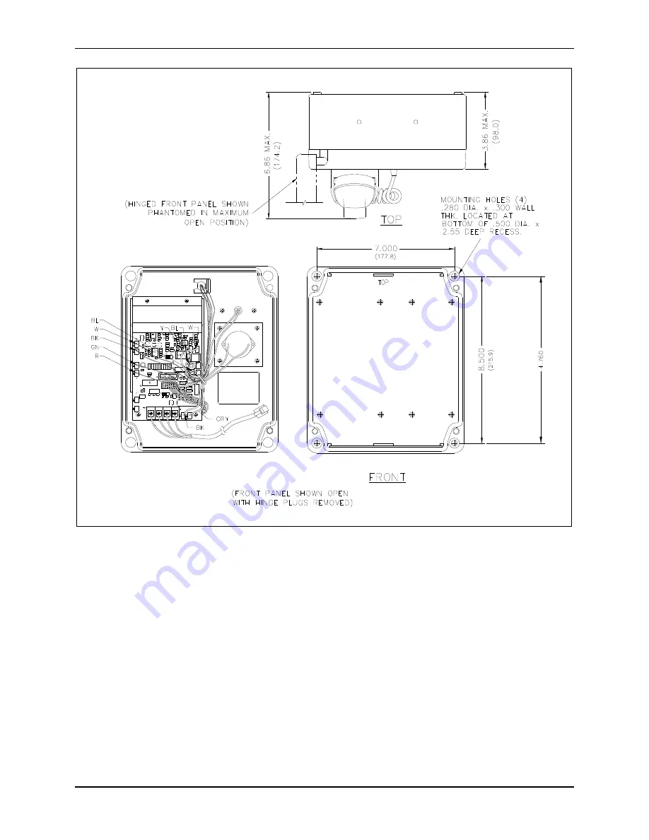
Figure 7. Model 341-001 Mounting Diagram
Page 1: ...L E O F C O N T E N T S Confidentiality Notice 1 General Information 1 Installation Guidelines 1 User Instructions USA 3 User Instructions Canada CP 01 Issue 8 Part I Section 14 1 3 CP 01 Issue 8 Part...
Page 2: ...re too harsh for a standard telephone The telephones operate the same as a standard telephone simply lift the handset and dial the desired telephone number The telephones are fully line powered and do...
Page 3: ...tom conduit entry makes water less likely to enter the unit at the conduit connection points 4 Use Teflon pipe joint tape or a thread sealing compound around the conduit threads to seal threaded conne...
Page 4: ...m is resolved This equipment uses the following USOC jacks RJ11CIt is recommended that the customer install an ac surge arrester in the ac outlet to which this device is connected This is to avoid dam...
Page 5: ...g a lightning storm A Cat5 data line lightning surge protector is recommended for telephones subject to any electrostatic discharge e g lightning Do not install jacks in wet locations unless the jack...
Page 6: ...STRIAL TELEPHONES PAGE 5 of 14 e standard ioms current release 42004 instr manuals 42004 339f doc 07 14 Figure 1 Bottom entry conduit installation details RECOMMENDED for non metallic enclosures Figur...
Page 7: ...patterns from the Northern Telecom Model NE 2525Q Series use the 7 875 4 00 inch hole pattern Four hole plugs are supplied for the unused holes When using the Model 232 001 Pole Mounting Kit use the 5...
Page 8: ...nect the free end of the modular telephone cord to the incoming subscriber line using the appropriate mating connector or connect the incoming line directly to the terminal strip 5 Replace the front p...
Page 9: ...t the enclosure to the wall using either four 1 4 20 machine screws with nuts and washers or 14 wood screws of appropriate length for the mounting surface Refer to Figure 7 3 Enter the rear enclosure...
Page 10: ...ub 42004 339F MODEL 226 002 341 001 AND 351 001 DIV 2 INDUSTRIAL TELEPHONES PAGE 9 of 14 e standard ioms current release 42004 instr manuals 42004 339f doc 07 14 Figure 7 Model 341 001 Mounting Diagra...
Page 11: ...t 4 Pull on the left side of the enclosure until the hinge plugs pull loose to separate the front half from the rear half Set the front half of the enclosure aside 5 Mount the enclosure on the wall us...
Page 12: ...14 e standard ioms current release 42004 instr manuals 42004 339f doc 07 14 9 Close the front half of the enclosure and secure it by replacing the four outermost screws 10 Check for proper telephone o...
Page 13: ...up To save the volume control setting jumper J4 which is factory set at positions 2 and 3 must be moved to positions 1 and 2 Specifications Electrical Typical Frequency response 300 to 3 000 Hz Inter...
Page 14: ...e switch Connections 6 5 foot 1 98 m modular line cord Dimensions outside 8 0 W 9 5 H 6 9 D inches 204 242 174 mm Mounting Four 0 280 inch diameter holes Weight 6 0 lbs 2 7 kg Model 351 001 Mechanical...
Page 15: ...ndset Assembly with 15 inch Armored Cord Volume Control and Noise Canceling 12512 001 Proximity Detecting Hookswitch Cradle Kit 12512 002 Hookswitch Cradle Kit 12516 001 Replacement Mounting Screw Kit...
Page 16: ...of the Contractor s personnel from the work site Re performance of services shall be Buyer s sole and exclusive remedy and in no event shall GAI Tronics warranty obligations with respect to services e...