


8
2.
Ensure that the clearance between the appliance
feet is at least 600 mm.
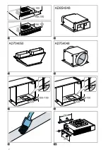
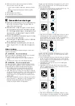
Preparing the unit
1.
For a base height lower than 130 mm, provide an
opening towards the front.
‒
If required, reinsert the section of the bottom
plate following installation.
2.
Mark the unit cut-out in accordance with the in-
stallation diagram and depending on the installa-
tion position.
→
3.
Establish a cut-out in the bottom plate.
4.
To change the filter, ensure that the base can be
removed or provide an opening of 600x100 mm.
5.
Make an air outlet in the plinth on the unit.
‒
Provide a minimum air outlet cross-section of
approx. 400 cm².
‒
Make the outlet opening in the base panel as
large as possible in order to keep draughts and
noise to a minimum.
6.
Ensure that the fitted unit is still stable after the
cut-outs have been made.
7.
Seal the cut surfaces so that they are heat-resist-
ant and waterproof.
→
8.
Remove any shavings.
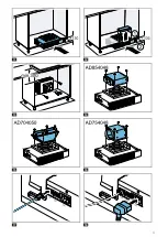
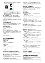
Preparing the appliance
▶
When installing on the unit's back panel, install the
enclosed bracket on the side of the appliance.
→
Sliding the appliance under the unit
WARNING ‒ Risk of electric shock!
Sharp-edged components inside the appliance may
damage the connecting cable.
▶
Do not kink or trap the connecting cable.
▶
Slide the appliance under the unit.
→
The appliance has rubber feet. It is not necessary
to secure it to the ground.
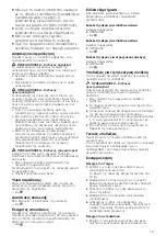
Screwing the appliance onto the unit back panel
WARNING ‒ Risk of electric shock!
Sharp-edged components inside the appliance may
damage the connecting cable.
▶
Do not kink or trap the connecting cable.
▶
Use screws to secure the appliance to the unit
back panel.
‒
Align the appliance horizontally.
‒
Observe the minimum clearance between the
lower edge of the hob and upper edge of the
fan module.
Establishing the piping
1.
Use the connecting piece or screw an air collector
box onto the appliance.
The air collector boxes are available as
2.
Secure the exhaust air pipe to the connecting
piece and seal it appropriately.
Screwing in accessories
1.
Screw in one air collector box for two flat ducts.
→
2.
Screw in one air collector box for two round ducts.
→
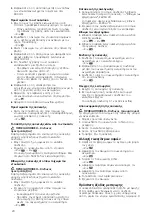
Connecting the appliance
1.
Use the control cable to connect the remote fan
unit and the fan.
→
2.
Ensure that the plug connections between the re-
mote fan unit and the fan click into place.
3.
Insert the mains plug of the remote fan module
into the mains socket.
→
Checking the functionality
1.
Check the functionality of the appliance.
2.
If the appliance does not work, check the control
cable's plug connections.
The connection sockets X1 and X2 are identical.
Removing the appliance
WARNING ‒ Risk of injury!
Components inside the appliance may have sharp
edges.
▶
Wear protective gloves.
1.
Disconnect the appliance from the power supply.
2.
Loosen the control cable.
3.
Loosen the exhaust connections.
4.
Pull out the appliance.
Replacing the odour filter
1.
Replace the odour filters at least once a year.
→
2.
Remove the cover from the fan module.
→
3.
Turn both knurled screws.
→
4.
Remove the odour filters and dispose of it.
→
5.
Remove the new odour filters from the packaging.
6.
Insert the new odour filters.
7.
Secure the cover.
Additional switching output
The appliance has an additional switching output
X16 (potential-free contact) that can be used to con-
nect other appliances, such as a ventilation system
that is available at the installation site. The contact is
closed when the fan is switched on, and is opened
when the fan is switched off.
Work must only be carried out on the additional
switching output by a qualified electrician in accord-
ance with the country-specific requirements and
standards.
The switching output is located under a cover. Max-
imum switching power 30 V/1 A (AC/DC). The sig-
nal that is connected to the contact must correspond
to protection class 3.
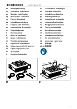
Summary of Contents for AR413122 AD854048
Page 2: ...2 3 4 5 6 7 8 9 10...
Page 3: ...3 11 12 13 14 15 16 17 18...
Page 19: ...19 III FI 1 2 150 mm 3 AD854048 4 AD704050 5 AD754048 6 1 1 10 kg 2 3 4 5 Poroton 1...
Page 37: ...37 ka III FI 1 2 150 3 AD854048 4 AD704050 5 AD754048 6 1 1 10...
Page 78: ...78 1 23 2 Reset LED Reset 5 5 Reset 24 3 4...
Page 79: ...79...
Page 80: ...80...