


11
GB947 HYDRAULIC POWER UNIT
8/23
1. Make sure electric motor is OFF.
2. Depressurize and disconnect hydraulic hoses from application.
3.
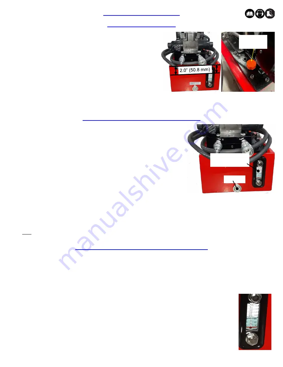
Remove air vent seat (reservoir cap) (946021) on the top plate of the
reservoir.
4.
Use a funnel to fill reservoir to about
2.00” (50.8
mm) from top of reservoir
plate.
5.
Wipe up any spilled oil and reinstall air vent seat (reservoir cap) (946021).
FILLING THE RESERVOIR
HOW TO SET
-
UP THE GB947
Guard against exceeding above 50°C (122°F). Various commercial thermometers are available to monitor oil temperature in the reservoir.
Continuous operation with reservoir oil temperatures in excess of 50°C (122°F) can cause permanent damage to the pump.
a. At oil temperatures above 60°C (140°F) HA
-
57 oil tends to thin and lose its ability to provide an adequate oil film in the ball bearings
and between various precision sliding surfaces in the pump mechanism. Furthermore, the oil additives tend to break down at
continuous operations above 60°C (140°F) reducing effectiveness of sealing materials.
b. Should over heating occur: Consider replacing the 2
-
1/2 gallon reservoir with a five gallon reservoir which has a higher heat dissipating
capacity. In general, a five gallon reservoir will take twice as long to reach 60°C (140°F) as a 2
-
1/2 gallon reservoir.
Hydraulic Oil: Standard hydraulic oil with a viscosity rating of 300 SUS @ 100 deg. F. and 50 SUS @ 210 deg. F.
Hydraulic Oil is not supplied by Gage Bilt. Use automatic transmissions oil, DEXRON III®, or equivalent.
Fire resistant hydraulic oil must be used to comply with OSHA regulation 1926.302 paragraph (d):
“
the fluid used in
hydraulic power tools shall be fire resistant fluid approved under Schedule 30 of the US Bureau of Mines, Department
of Interior, and shall retain its operating characteristics at the most extreme temperatures to which is will be exposed.
”
Fluid viscosity 300 SUS @ 100°F and 50 SUS @ 210° F is recommended for ambient temperatures 0 to 130° F.
RESERVOIR TEMPERATURE CONTROL CAUTION
DRAINING AND FLUSHING THE RESERVOIR
1. For best results, change oil every 300 hours or once a year, depending on use or
environmental conditions.
2.
Depressurize and disconnect hydraulic hoses from application.
3. Ensure motor is off and power is disconnected then place the Powerunit on a flat
stable surface.
4. Provide a suitable container to hold used oil. Using a hex key, unthread and remove
oil drain plug assembly (946031).
5.
Remove air vent seat (reservoir cap) (946021) on the top plate of the reservoir.
6. Tilt the pump and let used oil completely drain from reservoir into oil container.
7. Use a funnel to re
-
fill reservoir to about
2.00” (50.8
mm) from top of reservoir plate.
8. Wipe up any spilled oil from all surfaces including drain plug assembly (946031). Reinstall vent seat (946021).
9. Re
-
thread and tighten oil drain plug assembly (946031) to Powerunit.
10. Dispose of all used oil in accordance with the manufacturers safety datasheet.
Note: Clean oil filter screen periodically with nonflammable solvent, then blow dry before reassembling back onto the pump.
Oil Drain
Oil fill level and
temperature gage
Air vent seat
(946021)
Images may not reflect actual tool.