background image

First Flight Version 1.0 


Printed: 1/26/2008 

Appendix F – Installing USB Drivers on Windows 
Vista


Windows Vista is even less straightforward than XP for installing our drivers. Mainly this is 
because Microsoft is trying to make the process totally invisible to the user.  Therefore, if you have 
anything unusual about an installation, Windows gets confused. This is a step by step tour of the 
process. 

1.


Log into your PC as an administrator before you connect the interface card to your PC for 
the first time. 

2.


Connect your USB interface card and cable to your PC.  

o


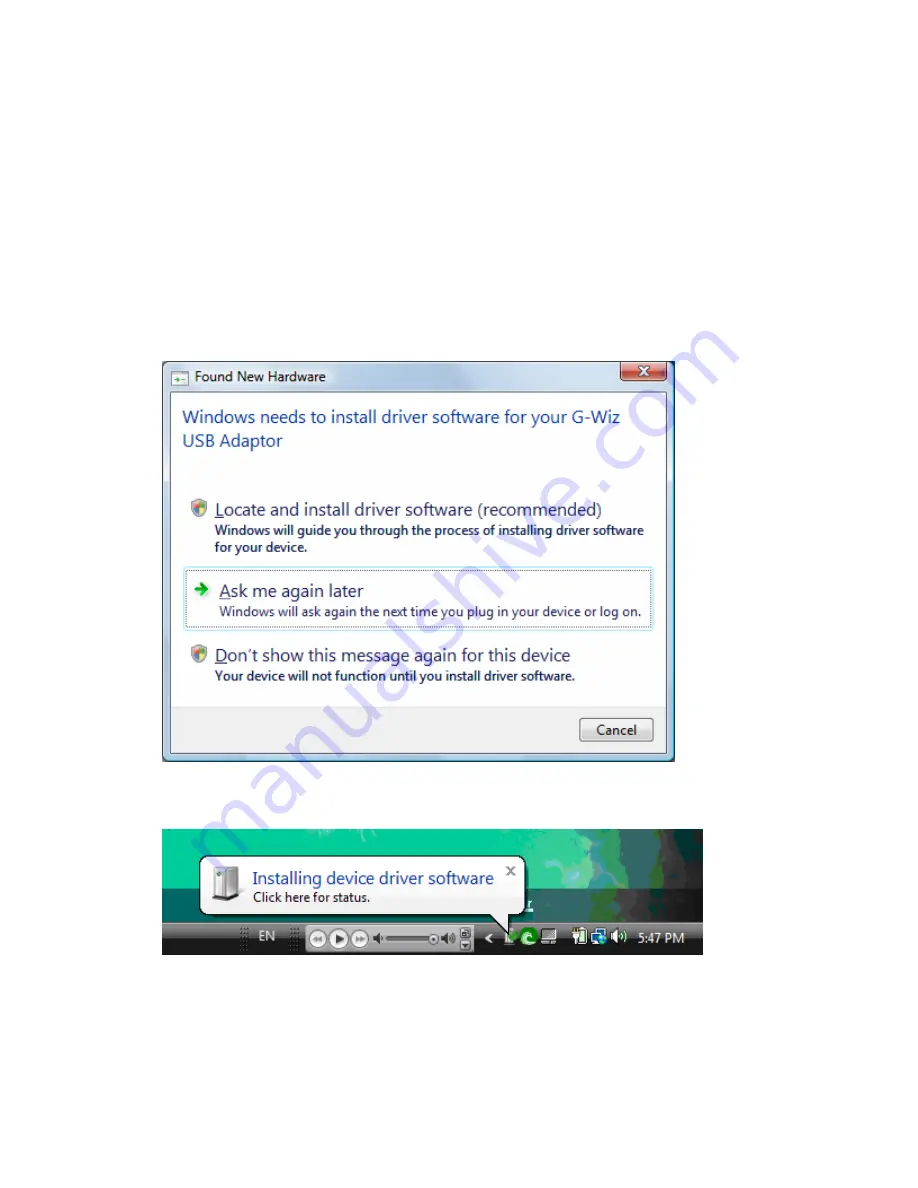
Windows Vista will display this dialog box: 

3.


Select 

Locate and install driver software

.   

o


If you select 

Ask me again later

, the installation will stop.  Unplug the USB card and 

then plug it back in to restart the installation process. 


Page 42 

Summary of Contents for HCX-100G

Page 1: ...F Fi ir rs st t F Fl li ig gh ht t Learning to Use Your G Wiz HCX Flight Computer Version 1 0 ...

Page 2: ...bility to use this device either separately or in combination with other equipment or for personal injury or loss or destruction of other property for experiment failure or for any other cause It is up to the user the experimenter to use good judgment and safe design practices and to properly pre test the device for its intended performance in the intended vehicle It is the user or experimenter s ...

Page 3: ...acceleration can cause these contacts to come loose resulting in an open circuit during flight This momentary or permanent break in your power connection will cause a catastrophic flight failure Similarly make sure your batteries are properly secured to prevent them from pulling wires out of the terminal block pins Recommended Battery Sizes Minimum Optimum Maximum CPU 7 5 volt 9 volt 12 volt Pyro ...

Page 4: ...ers on Windows XP 40 Appendix F Installing USB Drivers on Windows Vista 42 List of Procedures To Set Up the On Board Hardware 8 To Wire Up Your Power Connection 8 To Test the Setup 9 If You Do Not Hear the Correct Sequence 9 If You Hear the Correct Sequence Your Setup is Complete 9 To Prepare Your Flight Computer for Launch 12 To Read the Data from your Mini SD Card 14 To Save the Flight Data to y...

Page 5: ...or burns out before you ignite the sustainer motor Fly extreme altitude flights where the HCX can measure barometric altitude as high as 100 000 feet above sea level ASL Fly very high G short burn time motors when you configure the G Wiz HCX Flight Computer to use a break wire for launch detection Record user provided sensor data during flight when you use the BreakWire Analog input port to feed s...

Page 6: ...ccelerometer and barometer the HCX can also record data from the analog input port This port can be used for Mechanical detection of launch using a break wire Data recording from a user provided analog sensor The standard model the HCX 50 unit can accurately measure up to 56G of positive or negative acceleration while other models can accurately measure up to 224G The unique pyro port shunt plug i...

Page 7: ...ometric pressure to calculate altitude JP1 JP3 Safety Shunt Always use the safety shunt when your flight computer is controlling pyrotechnic events JP2 Pyro Current Jumper Sets high or low current operation for the pyro ports JP7 Cluster Stage Mode Jumper Defines when pyro port 1 is activated JP6 Communications Interface Socket Attach a G Wiz Interface Card here when you want to connect to your pe...

Page 8: ... HCX 200 224 G Interactive Hardware Features Integrated speaker and bright blue LED that is visible in bright daylight conditions indicate configuration and operational status before the flight The beeper and LED read out peak altitude after landing You can configure the unit to beep out the maximum airspeed too Configuring your Flight Computer Interface cards are available in either RS 232 or USB...

Page 9: ...ers The flight computer s configuration is stored in non volatile EEPROM The flight computer records its data on a removable Mini SD memory card The flight computer records acceleration pressure and events during the flight The Mini SD card can record multiple flights between downloads without risk of data loss The included SD card adapter allows convenient download of flight data to your personal...

Page 10: ... switch at whatever location is most convenient for the configuration of your rocket High current open drain power MOSFET switches safely initiate the pyrotechnic events A reverse protection diode protects your flight computer from the damage that could be caused by accidentally connecting a battery backwards The firmware prevents pyro port 1 from firing a sustainer motor if the rocket has already...

Page 11: ...hed to their pins Retain the antistatic bag to store your flight computer between uses Two nine volt battery adapters are included for your use If you misplace or damage either of the adapters please make sure to purchase high quality well constructed battery adapters Cheaply made adapters can lose contact under the stresses of flight computer acceleration potentially causing catastrophic failure ...

Page 12: ...rmatting your Mini SD card see Formatting Mini SD cards for use in your G Wiz HCX in the Using your Flight Computer section of the User Manual 3 Remove the JP2 jumper o These pictures show where the JP2 jumper is being removed o Make sure you store the jumper in a safe place until you need it again To Wire Up Your Power Connection 1 Run a wire from the positive CPU battery terminal TB2 pin6 marked...

Page 13: ... a double beep if the port has no continuity 6 There will be a one second pause and then the sequence will repeat from step b If You Do Not Hear the Correct Sequence 1 Note the exact status code readout 2 Refer to the status codes lists in Appendix B 3 Power the flight computer off 4 Make your changes to correct the problem o Is your SD Card installed correctly o Are all your jumpers enabled corre...

Page 14: ...the flight computer is designed to be mounted with two 4 40 thread machine screws Appendix C has a drawing of the board showing the locations and dimensions of the mounting holes and other important features Securely Anchor the Batteries Ensure that all batteries used to power the flight computer are securely mounted and anchored inside the rocket The typical G forces involved in even a model rock...

Page 15: ...shunt plug is nearer to the aft end of the rocket Provide Atmospheric Access for the Flight Computer You will need to drill a hole in the payload bay to equalize the pressure inside and outside of the rocket Otherwise the pressure sensor will be unable to detect altitude due to atmospheric pressure changes One 1 8 inch hole at least 6 inches below the nose cone will be sufficient for a rocket of 1...

Page 16: ...e flight computer 2 Listen to the flight computer status beep codes If they are incorrect a Shut down the HCX b Recheck your setup c Power it back up to check them again o A full list of the flight computer status codes is available in Appendix B If they are correct mount the flight computer in your rocket 3 Finish prepping your rocket including your motor based ejection 4 At the pad turn on your ...

Page 17: ... the number sequences until you power off the unit This chart shows some examples Altitude feet Beep Code 5 081 Beep beep beep beep beep 5 long beep 0 beep beep beep beep beep beep beep beep 8 beep 1 12 112 Beep 1 beep beep 2 beep 1 beep 1 beep beep 1 9 817 Beep beep beep beep beep beep beep beep beep 9 beep beep beep beep beep beep beep beep 8 beep 1 beep beep beep beep beep beep beep 9 The compu...

Page 18: ...z partners com Downloads install install html To Read the Data from your Mini SD Card 1 Make sure the G Wiz Flight Viewer program FlightView is installed on your computer 2 Put the Mini SD card into its SD card adapter 3 Plug the card into an SD reader attached to your computer 4 Open the FlightView program 5 On the toolbar click on the Open Flight Data File button or select File Open from the men...

Page 19: ...nd click the Open button to open the flight file 8 Click the Flight Information tab if you want to add detailed information on the rocket and motor you used for the flight 9 Click the Flight Summary tab for an overview of all the parameters measured during your flight 10 Click the Overlay Graph tab to see a graph of the measured and calculated data on the same time axis Page 15 ...

Page 20: ...s window 11 Click the other tabs to see graphs of the measured and calculated data in graphical form To Save the Flight Data to your Personal Computer 1 Click the Save Document as button on the FlightView main menu bar or select G Wiz Save As from the main menu 2 Navigate to the directory where you plan to store your flight data Page 16 ...

Page 21: ...th FAT or FAT32 file system on your personal computer For more information on all of the features available in FlightView see the Using FlightView Software chapter of the G Wiz HCX User Manual Conclusion Now that you have experienced the G Wiz HCX flight computer in action we strongly recommend that you read the G Wiz HCX User Manual It is available for download at the G Wiz web site http www gwiz...

Page 22: ... your answer Using the Safety Shunt Unless you are using motor ejection we recommend that you always include a pyro shunt in your flight computer setup When it is properly installed connecting JP1 and JP3 it protects the pyro ports from accidentally firing during setup or transport You should use the built in shunt JP 1 3 any time the HCX is mounted in the rocket in a position where the shunt plug...

Page 23: ...ration settings for the G Wiz HCX flight computer are Staging is for first stage Low altitude deployment is set for 800 feet English units are used No delays are put into any of the events If these settings work for your flight plan then you do not need to configure your flight computer The Communication Interface Card In order to change your configuration you first need to connect your flight com...

Page 24: ...he G Wiz serial interface does not require any drivers to be installed 4 After the drivers have finished installing start FlightView 5 Go into the Preferences menu 6 Click the G Wiz Connection Port drop down box and select the highest number COM port o This will usually be the most recently installed port If you know your flight computer interface is on a different port select it instead 7 Click O...

Page 25: ...tch your flight plan 3 Press Upload Exit when you are done 4 Disconnect the flight computer from FlightView 5 Power your flight computer off The new configuration will be loaded when the flight computer is powered on again You can find more detailed information in the Using FlightView chapter in the User Manual Page 21 ...

Page 26: ...flight computer before you set it up for flight When you connect to your personal computer you only need to set up the HCX for single battery operation Also your jumper settings are not important during the configuration process you do not need to set them until you set up your unit for flight Note When you fire the pyro ports in low current single battery mode you must use an electric match with ...

Page 27: ...Jumper Modes Jumper Position Number With Jumper IN With Jumper OUT JP 2 Pyro current selection System allows High Current two batteries must be used System limited to low current one battery can be used JP 7 Cluster or stage selection Stage mode enabled Cluster mode enabled JP 5 Breakwire Bypass Breakwire launch detection enabled User analog input 0 5v enabled Page 23 ...

Page 28: ...e safety shunt This picture shows the black jumper connector you remove from the JP2 jumper pins 4 Put all the other jumpers IN Your flight computer is now enabled for low pyro current You must pull the jumper OUT and use low current if you are using a single battery To Wire the Pyro Ports 1 Wire the drogue chute firing device to the two Apogee terminals TB1 pins 5 6 o Most electric match firing d...

Page 29: ...atus codes To Configure your Flight Computer 1 Connect your flight computer to your personal computer o See the instructions for connecting the flight computer in the Using FlightView Software section of the User Manual 2 Go into the Configuration menu 3 On the Main and Output tabs change the configuration settings to match your flight plan o If you have any problems consult the Configuring your H...

Page 30: ... to the safety shunt This picture shows the black jumper connector being installed on the JP2 Your flight computer is now enabled up for high pyro current To Wire the Pyro Ports 1 Wire the drogue chute firing device to the Apogee terminals TB1 pins 5 6 Davyfire 28b firing devices are not polarity sensitive 2 Wire the Main chute firing device to the LowAltitude terminals TB1 pins 7 8 To Wire Up You...

Page 31: ... not the pattern you hear refer to Appendix B for a list of the Flight Computer Status codes To Configure your Flight Computer 1 Connect your flight computer to your personal computer o See the instructions for connecting the flight computer in the Using FlightView Software section of the User Manual 2 Go into the Configuration menu 3 On the Main and Output tabs change the configuration settings t...

Page 32: ...ocated near the fin end of the flight computer next to the safety shunt 4 Put the JP7 jumper IN to enable the system for stage mode o The JP7 jumper is located just forward of the status LED on the far side of the board This photo shows both the JP2 and the JP7 jumper connectors being installed on their jumper pins Your flight computer is now enabled for high pyro current To Wire the Pyro Ports 1 ...

Page 33: ...e terminals 6 Then it will pause and cycle the beep pattern again If this is not the pattern you hear refer to Appendix B for a list of the status codes To Configure your Flight Computer 1 Connect your flight computer to your personal computer o See the instructions for connecting the flight computer in the Using FlightView Software section of the User Manual 2 Go into the Configuration menu 3 On ...

Page 34: ...computer next to the safety shunt This picture shows the jumper connector being removed from the JP2 pins 4 The other two jumpers must be IN Your flight computer is now enabled for low pyro current You must set the jumper to low current if you are using a single battery To Wire the Pyro Ports Wire the main chute firing device to the Apogee terminals TB1 pins 5 6 To Wire Up Your Power Connection 1 ...

Page 35: ... to your personal computer o See the instructions for connecting the flight computer in the Using FlightView Software section of the User Manual 2 Go into the Configuration menu 3 On the Main and Output tabs change the configuration settings to match your flight plan o If you have any problems consult the Configuring your HCX section in the Using FlightView Software chapter of the User Manual 4 Se...

Page 36: ...for high pyro current which is required when you use the HCX for any flight involving staging or clustering To Wire the Pyro Ports 1 Wire your main chute firing device to the Apogee terminals TB1 pins 5 6 2 Wire your cluster motor firing device to the Cluster Stage terminals TB1 pins 3 4 To Wire Up Your Power Connection 1 Wire a 9 volt battery for the computer to the CBatt terminals TB2 pins 5 6 m...

Page 37: ...onfiguration settings to match your flight plan o If you have any problems consult the Configuring your HCX section in the Using FlightView Software chapter of the User Manual 4 Select Upload and Exit 5 Disconnect your flight computer from your personal computer 6 Power your flight computer off and then on to load the new configuration into memory Once you ve tested your setup by listening to the ...

Page 38: ...ical 4 User Selectable Programmable Low altitude pyro channel activation Programmable Default is 800 feet ADC resolution 12 bits or 1 22 mV bit Analog Input Channel Range Resolution Input Range 0 to 5 0 VDC Resolution 12 bits or 1 22 mV bit Breakwire Input Switch Requirements Closed to open signals launch Sensor Sample Rate Selectable 66 67 to 500 samples per second Altitude readout Status LED and...

Page 39: ... JP7 IN low pitch beeps 3 After a half second pause the beeper gives a short warble 4 LED turns off 5 There is a half second pause 6 Starting with pyro port one each pyro port reports status with either a single quick beep for good continuity or a double beep if the port has incomplete continuity 7 A 1 second pause and then the sequence repeats from step 2 If you hear this sequence you have less t...

Page 40: ... your unit off 2 Attach a wire between the two Breakwire terminals TB2 pins 3 4 3 Connect your flight computer to FlightView 4 Go into the Configuration screen 5 Uncheck the Breakwire Launch Detect checkbox 6 Disconnect from FlightView 7 Power cycle your flight computer to continue Power On Self Test Failure POST Failure 1 Long warble 2 Half second delay 3 1 7 high pitch beeps giving a failure cod...

Page 41: ...itialize card Reformat or replace card 3 beeps Wrong file system on card Reformat card as FAT or FAT32 4 beeps SD card read error Probable cause bad card 5 beeps SD card not FAT formatted Reformat card as FAT or FAT32 6 beeps SD card partition table bad Reformat card as FAT or FAT32 7 beeps SD card partition not right type Reformat card as FAT or FAT32 8 beeps SD card read error Probable cause bad...

Page 42: ...First Flight Version 1 0 Printed 1 26 2008 Appendix C Mechanical Drawing When you design your flight computer s mounting system here are the important dimensions you need to know Page 38 ...

Page 43: ...ations GwizViewer 2 Double click the package icon named FTDIUSBSerialDriver 3 In your Utilities folder open the Terminal program 4 At the prompt type cd Library StartupItems FTDIReEnumerate and press RETURN 5 Type sudo pico FTDIReEnumerate and press RETURN 6 Type in your administrator password when requested by the system 7 Find this line in the terminal editor window Library StartupItems FTDIReEn...

Page 44: ...ded tour 1 Log into your PC as an administrator before connecting the interface card for the first time 2 Connect your USB interface card o Windows XP will display this dialog box 3 Select No not this time and press Next o Windows XP will now display 4 Select Install from a list or specific location Advanced and click Next o Windows will now display this dialog box Page 40 ...

Page 45: ...GWizViewer install directory and then navigate to the usbDrivers directory under it o The location shown here is the default installation directory if your main disk is C 8 Click Next o Windows XP will display this dialog box 9 Press the Continue Anyway button to continue the installation 10 Repeat steps 1 through 8 for the second driver Your computer is now ready to connect from FlightView to you...

Page 46: ... unusual about an installation Windows gets confused This is a step by step tour of the process 1 Log into your PC as an administrator before you connect the interface card to your PC for the first time 2 Connect your USB interface card and cable to your PC o Windows Vista will display this dialog box 3 Select Locate and install driver software o If you select Ask me again later the installation w...

Page 47: ... for drivers in Windows Update There is no way to tell it not to do so If you click on the Device Installation icon in the notification area of the taskbar you will see this progress window 4 Do not close this window o After searching for a few minutes Windows will display Page 43 ...

Page 48: ...c Show me other options o Windows will now display 6 Click Browse my computer for driver software advanced o Windows will now open a file browser dialog box 7 Navigate to the directory where you installed GWizFlightView and then to the usbDrivers directory under it Page 44 ...

Page 49: ...9 Click OK and Windows Vista will start to install the drivers o Windows will display 10 Click Install this Driver Anyway o When Windows tells you it has finished installing the drivers for the G Wiz USB Interface Card it will then tell you it has found a second device that needs a driver Page 45 ...

Page 50: ... manual you have any questions or problems with either your flight computer or the FlightView software please visit us on the web at http www gwiz partners com We maintain an FAQ on our web site In addition the latest versions of both FlightView and the HCX Firmware are posted there for download You can email us at support gwiz partners com Or write us at G Wiz Partners PO Box 320103 Los Gatos CA ...

Reviews: