


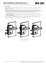


Installation, operating and maintenance instructions
Radio locks PRIME OFFICE 2170 (EN 179) for toughened glass doors
7
0-45648-3E-0-GB, modif. 1, sheet 7/20, Mod. No. G24578, www.g-u.com 01/2011
3
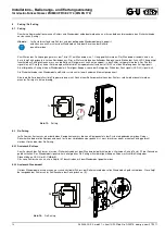
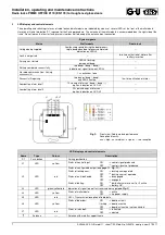
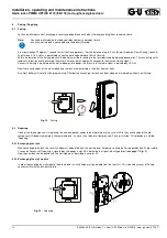
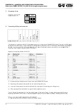
LED display and control elements
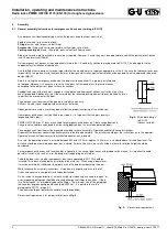
The operating and switching statuses of radio lock and wall module are indicated by means of several LEDs at the front of the wall module.
Here you will also find button 'S1' required for the Pairing procedure. The antenna of the wall module is accommodated on the right side of the
frame. Do not loosen the four fastening screws in order not to damage the antenna input connection.
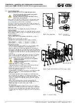
Fig. 3:
Front view / Radio module performance
Reception intensity:
+++
= high;
++
= medium;
+
= poor;
─
= no reception
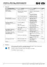
System signals
Status
Wall module
Radio lock
Voltage being supplied
Low buzzing sound during the boot process,
single beep when boot process completed;
indication on LED L4
---
Lock is not paired
---
two-time activation of motor after
battery insertion
Pairing has started
LED L5 flashing,
permanent beep
---
Pairing completed successfully
two beeps (beep – beep) /
Indication of signal force on LED L3
---
No radio communication / Pairing
unsuccessful
1 s continuous tone
---
Successful Repairing
two beeps (beep – beep),
only LED L2 active
five-time activation of motor
Low-battery alarm level 1
10 s beep at intervals (beep – beep –...)
option: indication on LED L2
---
Low-battery alarm level 2
20 s quick beeps at intervals /
option: indication on LED L2
---
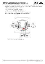
LED display and control elements
Name
Type
Colour
Description
S1
Push button
---
Pairing pushbutton
L1
LED
yellow
Status of control input:
ON
→
control signal produced
OFF
→
control signal not produced
L2
LED
red
Status of configurable output (
see page 11, Fig. 11
):
Status of locking cam:
ON
→
locking cam operated
OFF
→
locking cam not operated
Status of outside handle:
ON
→
disengaged
OFF
→
engaged
Status of battery:
ON
→
low-battery alarm level 1 or 2 active
OFF
→
battery OK
L3
LED
green/yellow/red
Indication of signal force of last received message (
see Fig. 3
)
L4
LED
yellow
Status of wall module:
ON
→
active
OFF
→
no power supply
L5
LED
red
ON
→
Transmission/reception of radio data
L6
LED
yellow
Status of door bus:
ON
→
door bus fault
flashing
→
door bus active
OFF
→
door bus inactive / not connected
L7
LED
red
Status of latchbolt:
ON
→
retracted
OFF
→
ejected
Antenna
---
Antenna with metallic support frame
S1
L1
L2
L3 L4
L5
L6
L7


