background image


01.06.2022 

Assembly instructions | G-Flexx 


G-

Rack UG & Co KG • Speckenbeker Weg 130e • D-24113 Kiel • Tel.: +49 431 

648060


Fax: +49 431 

64806-50


• Email[email protected] • www.g-rack.de 


4/23 

10


Connect the side frame with the front frame by screwing 
the wing bolts into the frame inserted nuts. 
 

11


Connection of two or more G-Flexx 

In each side tube of the front frame there are 4 wing bolts.


Only one of the wing bolts in each side tube is used to 
connect the base frames. 

Use the black wing bolts for connecting front frames!


12


Place the base frames side by side. 


If the height varies, make sure the leveling feet of both 
base frames are in the same position. 
The 

lowest

 wing bolt of the 

right

 G-Flexx fits into the 

insert nut of the left G-Flexx. 
The 

second

 wing bolt from the top of the

 left

 G-Flexx is 

fitting into the insert nut of the right G-Flexx.  
If the front frame is connected, connect the side frames 
the same way.


Summary of Contents for G-Flexx

Page 1: ... Front Banner Front Panel 7 Side Applications 7 Side Panels 8 Work Tops 8 Accessories 9 Quiver Board 9 Hook in tray for Quiver Board 9 Bar Top Tray 10 Hook in tray large 10 Speedrack 10 Shelves Set 11 Bottle Display 11 Ice Box with Sliding Top Set 11 Rack Slide Drawer 12 LED Light Bar RGBW 14 LED Light Bar 15 Worktop Lamp 15 Sliding door set 16 Lock for sliding door set 17 Door with hinges and loc...

Page 2: ...6 50 Email info g rack de www g rack de 2 23 The Counter 1 Base Frame G Flexx Item no fx bm 2 Place the base frame in an upright position and pull the front frames at an angle of 90 to each other 3 9 0 ca 90 Put the middle frame with the LONG bolts in the holes of the right front frame 4 Flap on the front frame completely 5 6 ...

Page 3: ...ail info g rack de www g rack de 3 23 7 8 Base Frame G Flexx Mini Item no fx bms Place the base frame in an upright position and pull the front frames at an angle of 90 to each other 9 For transportation we advise to fix the second side frame at the other side frame with the two bolts Unfasten the two screws for assembling the frame ...

Page 4: ...there are 4 wing bolts Only one of the wing bolts in each side tube is used to connect the base frames Use the black wing bolts for connecting front frames 12 Place the base frames side by side If the height varies make sure the leveling feet of both base frames are in the same position The lowest wing bolt of the right G Flexx fits into the insert nut of the left G Flexx The second wing bolt from...

Page 5: ... frames The bar will tolerate if it is not set up exactly in level But in order to have a good fitting of all parts a larger bar should be set up straight Otherwise small gaps between the front panels can appear Align the frame with the help of the built in small water balance by adjusting the leveling feet 14 Adjust the leveling feet to remove gaps Floor lower in the middle of the bar ...

Page 6: ...t panels must be into position before the bar top is mounted 16 17 Bar Top Item no xx ct Place the bar top on top of the front frame A position bolt on the upper tube of the front frame must fit into a hole on the underside of the bar top 18 If the bar top is in position fix it to the frame by tightening the screws ATTENTION Please hold on the bar board with one hand For building longer counter by...

Page 7: ...r front panel with the piping in the slot underneath the bar top 21 Side Applications Item no xx sfa The side application forms the lateral ending of the bar front There is one side application to use on the left side and one to use at the right side of the bar The upper side fits over the end of the bar top the vertical part is connected to the front frame with wing bolts Notice Use the green win...

Page 8: ...h the floor If not screw the feet to adjust the height 25 Side Panels Item no xx sc The Side Panels Front Panels can be used for covering the front for covering the backside of the base frames and for covering the sides of G Flexx and G Raxx modules The stainless steel rails are hooked into the gaps milling grooves in the tube as shown 26 Work Tops Item no xx wt The insert nuts at the underside of...

Page 9: ...ghtening all screws If using a sliding door set you have to attach the upper rail before fixing the worktop Accessories The rear edge of the quiver board fits over the black bolts of the frontframe 28 Quiver Board Item no xx zb4 xx zb4 1 Fix the quiver board as shown 29 30 Hook in tray for Quiver Board Item no xx zb24 The tray is attachted to the quiverboard two quivers are still usable The tray h...

Page 10: ...em no xx zb25 The tray is hooked to the frontframe of the G Raxx G Flexx instead of the quiverboard The tray is providing a higher level for the preparation of the drink still giving easy access to the GN containers in the worktop The tray holds two barmats 310 x 150 mm or one barmat 500 600 mm 33 Speedrack Item no xx zb10 There are two positions the speedrack can be used If it used on the side th...

Page 11: ...e They can be used in combination with a shelf bottle shelf and glassware basket Shelf Item no xx zb8 Place the shelf on the corner rails Insert shelf with cornered edge facing you 37 Bottle Display Item no xx zb1 For using the bottle display the corner rails are needed Put the display onto the rails You can use the bottle display without and with shelf 38 Ice Box with Sliding Top Set Item no xx z...

Page 12: ...ust be insert first by holding the rail a little lower at the end and shove just the rear end into the milling groove of the vertical tube at the back of the base frame The front end must be still free Then hold the rail horizontal and turn it sidewards towards the vertical tube of the base frame until you can set the free end into the milling groove Notice It is supposed to go very easy don t use...

Page 13: ... info g rack de www g rack de 13 23 44 45 46 47 48 Push and pull the drawer to check the movement If the drawer does not slide correctly check the position of the base frame the drawer rails and the drawer frame 49 Attention If there more than one drawer please use only one drawer at time Warning The drawers are designed for max 25 kg ...

Page 14: ... the bar top and lit on the front For remove you have to push the LED holder to the top Underneath the bartop a number of stainless steel clamps are mounted to the lower front edge of the bartop on the inside For assembly the LED holder just slides into the space of these clamps an additional clamp applies pressure to the LED holder and keeps it in place during handling Instructions how to use the...

Page 15: ...files underneath the bar top Plug the light bar over these profiles By turning the lamp the lighting can be dimmed 55 Worktop Lamp Item no xx zb33 The lamp is plugged in and secured underneath the bartop and illuminates a part of the worktop 56 Check the position of the screw before mounting the lamp The screw has to be inside the bushing 57 58 Plug the lamp underneath the bartop customers side Pu...

Page 16: ... fx sd Please mount the sliding door set before you fix the work tops Push the bottom rail from the outside at the base frame and the corresponding tube from inside 62 Connect the bottom rail and the corresponding tube by screwing the 4 wing bolts 63 Put the upper rail on the base frame as shown 64 Fix the upper rail at the base frame by attaching the work tops Don t forget to screw the wing bolts...

Page 17: ... into the grooves of the rails 66 Lock for sliding door set Item no xx sdl For mounting the lock the door in the front groove has to take position at the left side the door in the rear groove at the right Plug the lock into the two holes of the doors The key must be at the right 67 68 69 Door with hinges and lock Item no xx hd The corner rails are hooked into the gaps milling grooves in the tube a...

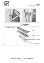
Page 18: ...G Speckenbeker Weg 130e D 24113 Kiel Tel 49 431 648060 Fax 49 431 64806 50 Email info g rack de www g rack de 18 23 70 71 Bar Top Extension Item no xx zb31 The Bartop Extension consists of cover plate drip plate support plate cut out for side application 81 ...

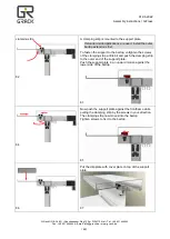
Page 19: ...st To fasten the support to the bartop untighten the screws of the clamping strip a little bit and push the clamping strip to the outer end of the support plate Push the support plate in an upward motion against the lower side of the bartop 83 84 Now push the support plate against the frontframe while pulling the clamping strip by the screws in your direction The clamping strip now moves into the ...

Page 20: ...leak in intake line Punctured pump diaphragm Defective pump check valve Crack in pump housing Debris in check valves Motor Fails to Turn On Pump or equipment not plugged in electrically Loose wiring connection Pressure switch failure Defective motor or rectifier Frozen cam bearing Pump Fails to Turn Off after Discharge valves are Closed Depletion of available liquid supply Punctured pump diaphragm...

Page 21: ...switch it back on again Press the ON button of the corresponding channel within 3 secs If the LED flashes repeatedly the controller has been deleted from the remote control The procedure for deleting a controller from a channel having multiple controllers is the same except that only the power supply to the controller concerned is interrupted Control Pressing the ON button for a longer time switch...

Page 22: ...6 2022 Assembly instructions G Flexx G Rack UG Co KG Speckenbeker Weg 130e D 24113 Kiel Tel 49 431 648060 Fax 49 431 64806 50 Email info g rack de www g rack de 22 23 Control panel on hand held transmitter ...

Page 23: ...aning with dishwashing and water or plastic cleaner or glass cleaner ATTENTION Don t use abrasive or solvent For little scratches use car polish paste Digitally imprinted materials Cleaning with dishwashing and water or plastic cleaner or glass cleaner ATTENTION Don t use abrasive or solvent Work tops Cleaning with dishwashing and water or plastic cleaner or glass cleaner ATTENTION Don t use abras...

Reviews: