
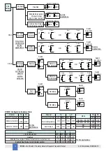

D1033
- SIL 2 Switch / Proximity Detector Repeater Transistor Output
G.M. International ISM0043-15
12
8
8
7
7
6
6
5
5
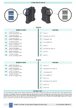
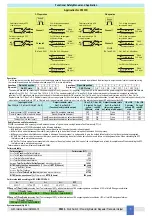
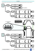
CH3
Setting
Line fault
detection
ON
IN / OUT
Operation
NO-NC or
NC-NO
NO-NO or
NC-NC
ON
OFF
Disabled
(contact / proximity sensor)
Enabled
(proximity sensor or contact
with terminating line resistor)
OFF
CH4
Setting
Line fault
detection
ON
IN / OUT
Operation
NO-NC or
NC-NO
NO-NO or
NC-NC
ON
OFF
Disabled
(contact / proximity sensor)
Enabled
(proximity sensor or contact
with terminating line resistor)
OFF
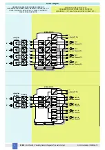
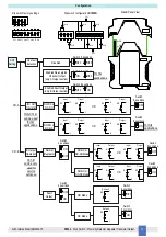
Input Output
Input Output
Output
Input
Output
Input
9
NO
10
OR
NC
9
10
9
NO
10
OR
NC
9
10
7
NO
2
NC
7
2
7
NO
2
NC
7
2
Input Output
Input Output
Output
Input
Output
Input
11
NO
12
OR
NC
11
12
11
NO
12
OR
NC
11
12
8
NO
6
NC
8
6
8
NO
6
NC
8
6
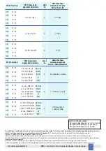
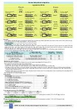
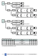
D1033Q Configuration Summary Table
Channel
IN/OUT Operation
NO-NC or NC-NO
NO-NO or NC-NC
SW1-2
OFF
SW1-4
OFF
ON
1
2
Channel
Line fault detection
Disabled
(contact/proximity sensor)
Enabled
(proximity sensor or contact with terminating line resistor)
SW1-1 SW1-3
1
2
ON
OFF OFF
ON
ON
SW1-5 SW1-7
3
4
OFF OFF
ON
ON
SW1-6
OFF
SW1-8
OFF
ON
3
4
ON
For SIL applications.
For SIL
applications.
For SIL
applications.
For SIL applications, all DIP-SWITCHES must be ON.
For SIL applications.


