G-Force CU36B6A Manual Download Page 9


Modes 


For different type of inputs you can employ diffent modes: 

 
Switch mode 

means the virtual button will be pressed when 1) the button is pressed and 2) the button is 

released. 

Switch on mode 

activates virtual button only when the real button is pressed 

Switch off mode

, on the contrary, activates virtual button only when the real button is released 

Soft switch mode 

will act as software button fixation: when you pressed the button for the first time the 

virtual button will be activated, when you press it the second time - virtual button is deactivated. 

Encoder mode 

is activated automatically for encoders set in the designated section. In this mode the 

activation of encoder positions is stored, and you can spin the encoder with a drill - and the board will store 
them and feed into the PC gradually, according to the timers set (see below)  

 
Shifts 


After defining shifts in the designated section of the MMjoySetup, you can assign different virtual buttons to 
the same hardware shift combination  

 
Timers 


You can set the duration of timers in the designated section of the configurator. 

Timer on 

sets the time for 

which your virtual button will be pressed. 

Timer off 

sets the time for the period when you will not be able to 

activate the virtual button again. Consider using an encoder for example. You can spin the handle really fast, 
and the PC will not be able to register the button presses properly. Setting the timers for encoder will let the 
PC receive stable length of virtual button presses. The other case it may be useful for is a bad shimmering 
button - when holding it will give you multiple unwanted virtual button presses. This may be avoided by 
employing timers.  

 
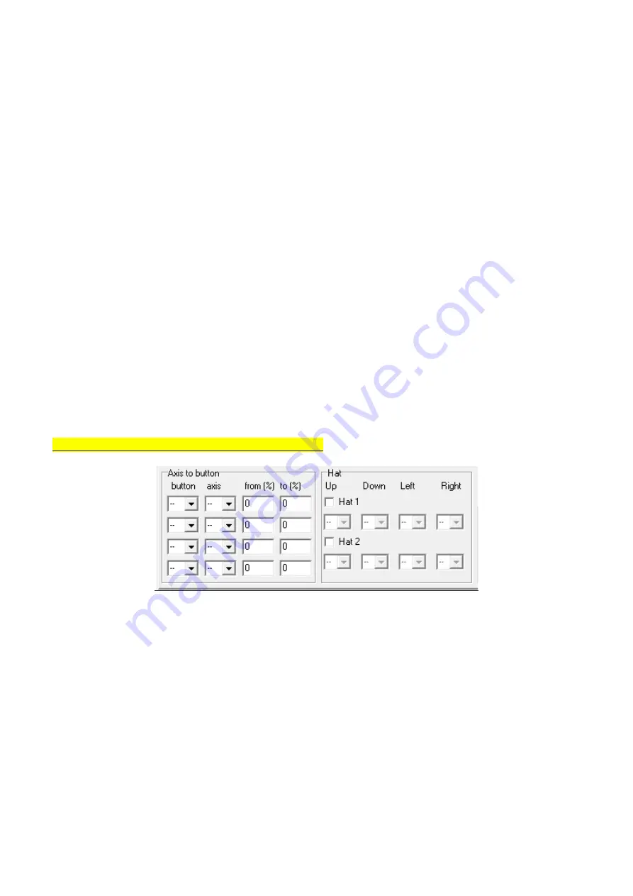
Advanced functions: Axis to buttons, Hats and Encoders  


These menus will allow you to enable functions like axis increments (e.g. from 100% to 0% in one click), and 
recognition of your buttons as hats or encoders.


Summary of Contents for CU36B6A

Page 1: ...32 Bit Joystick Interface CU36B6A Manual english V 1 For more info and support please visit our wesite https www g force sk...

Page 2: ...he pins on the PCB or connect using 3 pin and 2 pin cables Pin header has standard 0 1 2 54mm pitch You can also use the IDC 16P connector to connect buttons with flat AWG wire 36 digital inputs for b...

Page 3: ...ed to a rotary encoder All main types supported Maximum can be connected 6 encoders to 12 buttons input In the MMJoy2 software you can set all the encoder parameters Always use negative number for the...

Page 4: ...ng Simple potentiometer wiring for axe 1 example 8 direction POV hat switch Connect a hat switch or even make your own by connecting any four buttons of your choice Diagonal directions are made by pre...

Page 5: ...re the options as they are listed in the software Mandatory stuff Source In Source dropdown you have to select the type of axis input Virtual in this mode you will emulate axis changes by buttons More...

Page 6: ...ll range Another option is set it to manual and define top center and bottom values in the following fields The options with center w center will be helpful if you have the axis with asymmetrical move...

Page 7: ...f button assignment options Choose your source Remeber there are two options for buttons You can either make a button matrix or a shift register board You can define your input for buttons in the foll...

Page 8: ...lighting up in red This will help you later in mapping hardware buttons to virtual buttons and functions Timers and shifts This menus will allow you to set up to 3 types of delay for your switches an...

Page 9: ...hifts After defining shifts in the designated section of the MMjoySetup you can assign different virtual buttons to the same hardware button shift combination Timers You can set the duration of timers...

Reviews: