14
FITTING THE CLAMP ASSEMBLY (FIG.6)
Two sockets (one either side) are incorporated into the
rear of the machines fence. These sockets are for
positioning the Clamp Assembly.
Fit the clamp to the retaining socket that best suits
the cutting application, ensuring that it is fully pushed
down.
Using a screwdriver, tighten the clamp assembly lock
screw to lock the pillar of the clamp into the fence
socket, Fig.6.
Place the workpiece to be cut onto the saw table,
against the fence and in the desired position.
Adjust the clamp using the thumbscrews and hand-
wheel so that it securely holds the workpiece to the
saw table.
Conduct a ‘dry run’ with the power disconnected.
Ensure that the Clamp does not interfere with the path
of the blade, or with the path of any other part of the
cutting head as it is lowered.
SETTING THE TABLE SQUARE WITH THE BLADE
Make sure that the electrical plug is removed from the
power point.
Push the saw arm down to its lowest position by
pressing the release latch, Fig.7, and engage the
release knob to hold the saw arm in the transport
position, Fig.8.
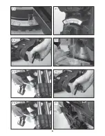
Fit the mitre lock handle (Fig.9).
Rotate the table until the pointer is positioned at 0º.
Tighten the mitre lock handle. (Fig.10)
Loosen the bevel lock and set the saw arm at 0º bevel
(the blade at 90º to the mitre table). (Fig.11)
Tighten the bevel lock, Fig.12.
Place a set square against the table and the flat part
of the blade (Fig.13).
NOTE. Make sure that the square contacts the flat
part of the saw blade, not the teeth. Rotate the blade
by hand and check the blade-to-table alignment at
several points. The edge of the set square and the
saw blade should be parallel.
If the saw blade angles away from the set square,
adjust as follows:
Loosen the bevel lock. (Fig.15)
Use 10mm spanner or adjustable spanner to adjust
the lock nut (Fig, 16), make sure the edge of set
square and saw blade should be parallel.
Tighten the bevel lock.
Loosen the screw holding the pointer of the bevel
scale and adjust the position of the pointer so that it
accurately indicates zero on the scale. Retighten the
screw, Fig.17.
Retighten the bevel lock and the lock nut securing the
0° bevel adjustment screw.
NOTE. The above procedure can also be used to
check the angle of the saw blade to the table at 45º
bevel angle. The 45° bevel adjustment screw is on the
opposite side of the saw arm.
TRENCH DEPTH ADJUSTMENT
In its normal position, the trenching stop permits the
saw blade to cut right through a workpiece.
To adjust the trench stop pull out the release knob out
and fully raise the saw arm (Fig.18)
When the saw arm is lifted, the trenching stop can be
adjusted so that the trenching depth adjustment
screw contacts the stop as the saw arm is lowered.
Deploy the stop by moving it outwards, Fig.19. If the
trenching stop wont move, slightly loosen the screw
using a crosshead screwdriver.
This restricts the cut to a “trench” in the workpiece.
The depth of the trench can be adjusted with the
trenching depth adjustment screw and locked in
position with the trenching depth lock nut (Fig.20).
OPERATION
Hold the operating handle firmly and squeeze the
switch trigger, (Fig.21).
Press the release latch (Fig.22).
When the blade is at its maximum speed
(approximately 2 seconds), lower the blade through
the workpiece (Fig.23). After completing the cut,
release the switch trigger and allow the saw blade to
stop rotating before raising the blade out of the
workpiece. Wait until the blade stops before removing
the workpiece.
CROSS-CUTTING (WITHOUT SLIDING FUNCTION)
To saw narrow pieces of wood, the slide function is
not necessary. In these cases, ensure that the slide
lock is screwed down to prevent the saw arm from
sliding, Fig.24.
A crosscut is made by cutting across the grain of the
workpiece. A 90º crosscut is made with the mitre
table set at 0º. Mitre crosscuts are made with the
table set at some angle other than zero.
Pull on the release knob and lift the saw arm to its full
height.
Loosen the mitre lock. Rotate the mitre table until the
pointer aligns with the desired angle. Retighten the
mitre lock.
WARNING. Be sure to tighten the mitre lock before
making a cut. Failure to do so could result in the table
moving during the cut and cause serious personal
injury.
Summary of Contents for FXAJ1G-ZP8-210C
Page 2: ...2 1 2 13 5 1 12 8 16 1 17 4 6 9 10 19 14 11 18 3 7 15 ...
Page 3: ...3 1A 26 22 23 25 28 20 27 21 29 24 ...
Page 4: ...4 2 3 4 5 6 7 9 8 ...
Page 5: ...5 10 11 12 13 14 15 17 16 ...
Page 6: ...6 18 19 20 21 22 23 24 25 ...
Page 7: ...7 26 27 28 ...
Page 90: ...90 ...


