background image

Wiring shown overleaf will disconnect the battery when you

remove the jack plug from the input, and also when a DC

plug is inserted.
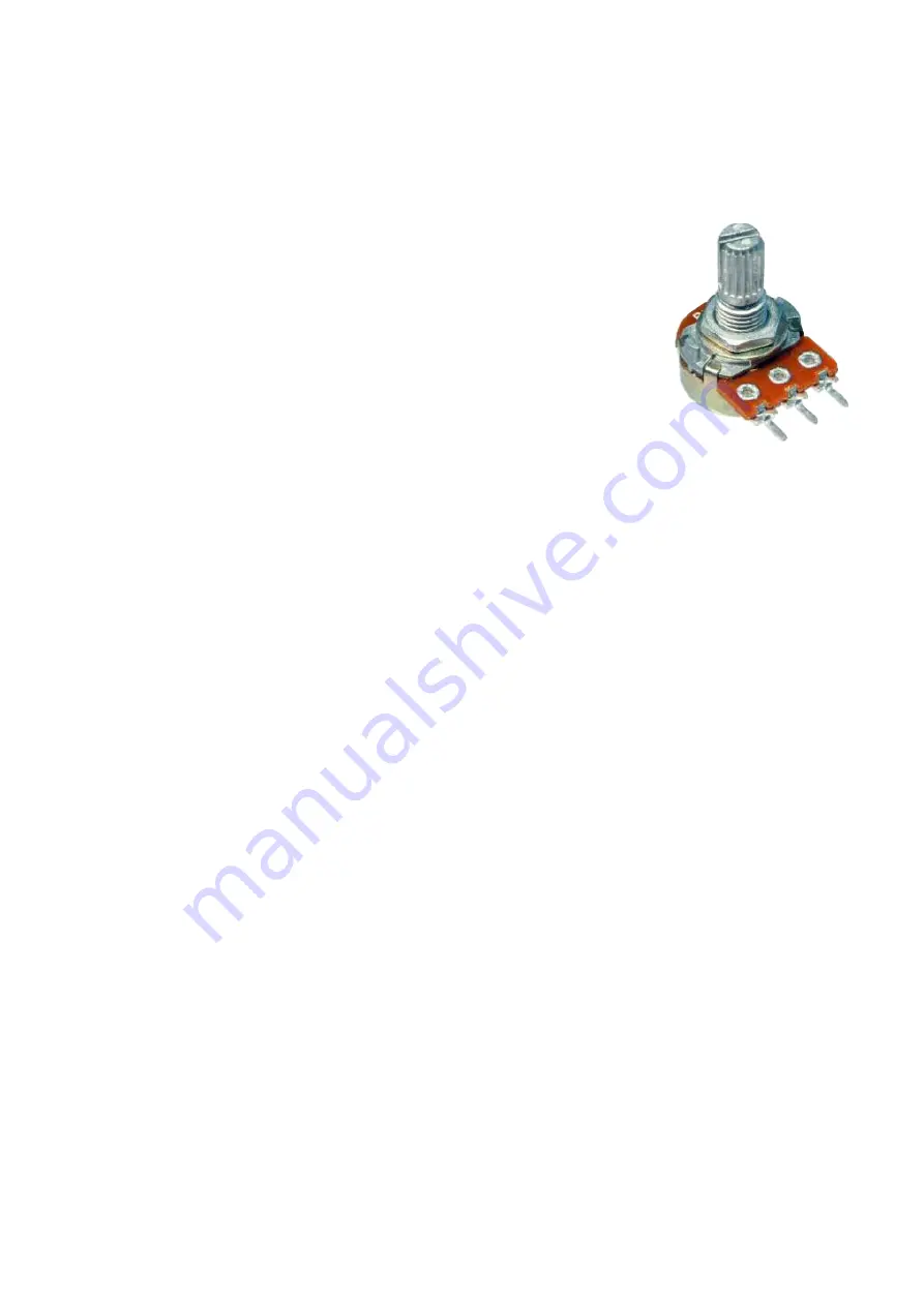
Snap the little metal tag off the pot to mount it

flush in the box.
You MUST use some kind of heat sink on the

legs of the transistors and diodes when

soldering. They aren’t keen on heat. Any more

than 3-4 seconds of iron and they’re toast.
Recommended assembly order:

Resistors, Caps, Transistors, Diodes, Wires, Pots
I’ve incorporated the Current Limiting Resistor for the LED

into the board for your pleasure.

Be VERY careful when bending

the legs of the 1N34A.

The case breaks very easily. I recommend using needle-

nosed pliers pressed up against the case to grip the leg,

then bend it with your fingers so no pressure is directly

applied to where the leg enters the casing. That does mean

you’ll have to bend them past 90° to get them to fit the hole,

and have the case sitting well above the PCB (or you could

seat them vertically like the 1N4001), but better than broken

diodes.

1    2

    3

Summary of Contents for SweetyPuss

Page 1: ...SweetyPuss High Octane Octave Up Fuzz PedalParts co uk ...

Page 2: ...K R21 10K R22 10K R23 1K R24 100K R25 100R R26 2K2 CLR C1 10u C2 10u C3 10u C4 10u C5 10u C6 10u C7 10u C8 10u C9 1n C10 100n C11 10u C12 10u C13 10u C14 100u C15 1n C16 10p Q1 5 2N3904 D1 2 1N34A D3 1N4001 GAIN 50KB TONE 10KB VOL 50KB GREMLIN ALERT No label on the IN pad Very high gain circuit You WILL pick up radio before you box it up Wow that s a lot of 10u caps ...

Page 3: ...tors Caps Transistors Diodes Wires Pots I ve incorporated the Current Limiting Resistor for the LED into the board for your pleasure Be VERY careful when bending the legs of the 1N34A The case breaks very easily I recommend using needle nosed pliers pressed up against the case to grip the leg then bend it with your fingers so no pressure is directly applied to where the leg enters the casing That ...

Page 4: ...the switch guess what You ve probably made a mistake with the switch Solder some nice long lengths of wire to the board connections for 9V GND IN and OUT Connect IN and OUT to the jacks as shown Connect all the GNDs together twist them up and add a small amount of solder to tack it Connect the battery lead to the 9V wire same method Plug in Go If it works crack on and do your switch wiring If not ...

Page 5: ... It doesn t matter how they all connect as long as they do This circuit is standard Negative GND Your power supply should be Tip Negative Sleeve Positive That s the same as your standard pedals Boss etc and you can safely daisy chain your supply to this pedal Now GO CHURN OUT THE OCTAVE UP FUN PedalParts co uk L E D BOARD OUT BOARD 9V BOARD GND BOARD GND BOARD GND BOARD INPUT BATTERY IN OUT L E D ...

Reviews: