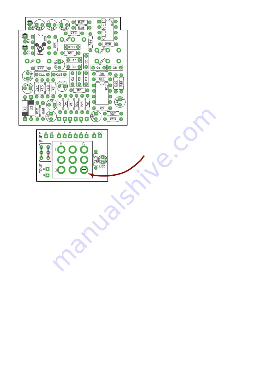
The Buffered/True-Bypass selection is
designed for a 2.54mm-pitch miniature slide
switch.
If you prefer to hardwire one way or the other,
wire in jumpers as shown above. Red for True
Bypass, blue for Buffered.
Anode (+) leg of electrolytic caps go into the
square pad.
Cathode (-) leg of diodes and the LED go into
the square pads.
Snap the little metal tag off the pots to mount
them flush in the box.
You should use some kind of heat sink on the
legs of the diodes when soldering. They aren’t
keen on heat. Any more than 3-4 seconds of
iron and they’re toast. Use sockets for the ICs
or be extra careful with them too.
Footswitch lugs should be horizontal and
inndicated above.
The current limiting resistor for the LED goes
into the spot marked ‘CLR’ on the
daughterboard. We supply 2K2.
Be VERY careful when bending the legs of the
germanium diodes. The glass case is very
fragile and likely to break. Hold the leg with
some needle-nosed pliers against the case,
and bend the leg with your finger so the
pliers are taking any strain away from it.
To give yourself more clearance when
mounting the circuit into your enclosure,
C17 and C20 can be bent over the adjacent
components as shown in the cover image.
Connect the two PCBs together using pads
1 2 V G 3 4
Your jacks connect to G / IN and G / OUT on
the daughterboad.
DC connections are G and V pads next to
‘TRUE’.
PCB Layout ©2017 Pedal Parts Ltd.
PART SUBSTITUTIONS
The circuit benefits from some extra bass in
both the gain and clean sections:
C2
100n (clean)
C6
120 - 150n (gain)
The Tone (Treble) control has a more useful
range if you increase
C14
to 6n8 or 8n2.
Footswitch lugs should be horizontal
Summary of Contents for Klone V4
Page 7: ...Wire it up switching board ...
Page 8: ...Wire it up true bypass ...


