Futurecom Siren & Lights Interface Module Install And Configuration Manual Download Page 21


8A089X01 Rev 1 

SLIM Installation Manual 


3/23/2018 


Page 21 of 61 

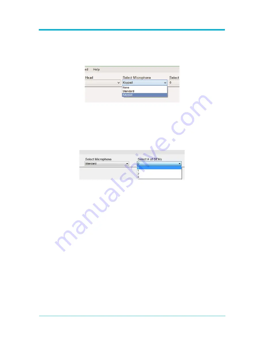
2.5.1.1.2 Selecting A Microphone 

The drop-down for selecting a microphone will be available once the radio control head is 
selected. Setting the microphone will not change the radio image displayed in the left pane 
of the screen. The different microphones available may impact the options available in the 
Map Actions screen. It is important to select the correct equipment. 


Figure 2-16  Microphone Selection 

2.5.1.1.3 Selecting DEKs 

The  drop-down  box  for  selecting  the  number  of  DEKs  will  be  available  once  the  radio 
control  head  is  selected.  Setting  the  number  of  DEKs  will  not  change  the  radio  image 
displayed in the left pane of the screen. The number of DEKs available may impact the 
options available in the Map Actions screen. It is important to select the correct equipment. 


Figure 2-17  DEK Selection 


Summary of Contents for Siren & Lights Interface Module

Page 1: ...Futurecom Systems Group ULC Siren Lights Interface Module Install and Configuration Manual...

Page 2: ...8A089X01 Rev 1 SLIM Installation Manual 3 23 2018 Page 2 of 61 NOTES...

Page 3: ...pter 1 Introduction 9 1 1 Mobile Radio Description 9 1 1 1 Minimum Requirements 9 1 1 2 Specifications 10 Chapter 2 Pre Installation and Configuration 11 2 1 Introduction 11 2 2 Radio Preparation 11 2...

Page 4: ...ANTROL 47 4 5 1 Siren Pre Installation 47 4 5 2 Data Connection 47 4 5 3 Audio Connection 48 4 5 4 Expansion Board Installation 48 4 6 Whelen CENCOM 51 4 6 1 Siren Pre Installation 51 4 6 2 Data 51 4...

Page 5: ...on 20 Figure 2 16 Microphone Selection 21 Figure 2 17 DEK Selection 21 Figure 2 18 Siren Before After Selection 22 Figure 2 19 Siren Control Head Selection 22 Figure 2 20 Navigation Buttons 23 Figure...

Page 6: ...rietary Statement 2018 Futurecom Systems Group ULC Printed in Canada All Rights Reserved No part of this document or any software included with it may be reproduced and distributed without the prior w...

Page 7: ...t or item and pay transportation expenses for such replacement at no charge to Buyer who shall provide labor for the removal of the defective component or item and installation of its replacement at n...

Page 8: ...and other countries preserve for Futurecom certain exclusive rights for copyrighted computer programs including but not limited to the exclusive right to copy or reproduce in any form the copyrighted...

Page 9: ...llers 1 1 Mobile Radio Description 1 1 1 Minimum Requirements Table 1 1 Minimum Requirement Items Requirement Mobile Radio Motorola APX 6500 Motorola APX 6500Li Motorola APX 7500 or Motorola APX 8500...

Page 10: ...able 1 2 Specifications General Input Voltage 13 8 VDC 20 Main Input Fuse 2 A Typical Power Consumption 200 mA Operating Temperature 30 C to 70 C Storage Temperature 40 C to 85 C Reverse Polarity Prot...

Page 11: ...Before configuring the Module first ensure compatible radio hardware is used The mobile radio must utilize a compatible TIB to support integration with the Module If needed the TIB can be upgraded to...

Page 12: ...where Third Party capable buttons may be programmed depending on the type or location of the button The five classifications of buttons are Control Head buttons Keypad buttons Keypad Mic buttons DEK b...

Page 13: ...8A089X01 Rev 1 SLIM Installation Manual 3 23 2018 Page 13 of 61 Figure 2 3 O3 Control Head Third Party Capable Buttons Figure 2 4 O7 Control Head Third Party Capable Buttons...

Page 14: ...ics Configuration submenu open the Controls submenu select Keypad and then for each desired button set the button s feature to Third Party Note that keypad buttons are the same across all radio device...

Page 15: ...Set Button s Feature Figure 2 7 Keypad Microphone 2 2 1 2 4 DEK s Use the CPS to program DEK buttons as one normally would but set their feature to Third Party For example open the CPS from the left...

Page 16: ...on will be set to perform one or more CPS defined actions and also will be used with the Module then be sure to consider setting a desired Third Party Notification Error Strategy If for any reason the...

Page 17: ...e Module cannot change the button type of a siren feature so time should be taken to setup the siren carefully while noting the functionality and type of each button during programming This informatio...

Page 18: ...ia its 25 pin RADIO PROGRAM port Using the Module s programming cable included in kit TT06296AA connect the Module to a PC The PC should already have the Siren Light Interface Module Programming Utili...

Page 19: ...uring programming to ensure the Module is powered on Please refer to the Section 3 4 Wiring for additional wiring details Figure 2 12 Power Harness Connection 2 4 3 Programming Utility Open the Module...

Page 20: ...stomize options available based on their equipment 2 5 1 1 Modify Devices Screen The Modify Devices screen is the starting point for setting up a new Module configuration Before the Module can be conf...

Page 21: ...impact the options available in the Map Actions screen It is important to select the correct equipment Figure 2 16 Microphone Selection 2 5 1 1 3 Selecting DEKs The drop down box for selecting the num...

Page 22: ...gure 2 18 Siren Before After Selection 2 5 1 1 5 Selecting A Siren Control Head Depending on the siren light controller selected there may or may not be multiple control head options The drop down box...

Page 23: ...ainder of the configuration Figure 2 20 Navigation Buttons 2 5 1 2 Map Actions Screen The Map Actions screen is where the Module configuration truly takes place It is here that the interaction between...

Page 24: ...vice or accessory However the numeric keypad is not unique between devices The number 1 on the O9 control head is the same number 1 on the keypad mic This is a feature of the radio Users familiar with...

Page 25: ...king audio from the radio microphone and outputting it to the light siren controller for amplification and output to a siren speaker The radio and Module do not output PA audio by default PA audio is...

Page 26: ...from The device label will match one of the devices shown in the top left input panel diagrams The device label is most helpful when two or more devices share similar input names Figure 2 24 Device Co...

Page 27: ...e that mode simultaneously The function list for PA will allow an optional siren button to be activated along with radio PA in the event that it is necessary and desired to put both devices into a PA...

Page 28: ...ts should not be mapped to other Inputs Doing so can lead to operating and configuration issues If needed multiple Inputs can be mapped to the same output Action 2 5 1 2 5 Action Consolidation Action...

Page 29: ...8A089X01 Rev 1 SLIM Installation Manual 3 23 2018 Page 29 of 61 Figure 2 29 Action Consolidation...

Page 30: ...ft side of the status line is used for connection messages The utility automatically detects the connection or disconnections of a compatible Module When a Module is connected the utility attempts to...

Page 31: ...save location The Save As menu option allows a user to save changed made to a configuration and prompts the user for a file name and save location even if the configuration was previously associated...

Page 32: ...e Module button on the Map Action screen but is available at any time through the menu Figure 2 35 Transfer Menu 2 5 1 4 3 Advanced Menu The Write Firmware menu option allows a user to re flash a conn...

Page 33: ...e 33 of 61 2 5 1 4 4 Help Menu The User Guide menu option allows a user to load the Module s user guide this manual The About menu option allows a user to view information about the programming utilit...

Page 34: ...nce working with automotive electronics and general knowledge of safety procedures related to such systems If a butt connector or splice may be exposed to moisture then waterproof connectors must be u...

Page 35: ...g an awl or similar tool scribe the mounting surface where the mounting holes are to be drilled Make sure that this mounting area allows sufficient ventilation for the Module Caution Mounting the Modu...

Page 36: ...e battery Do not use circuit breakers with this product IMPORTANT Wires connecting to the SLIM power harness and GPIO port have the proper terminals pre installed If the customer needs to re terminate...

Page 37: ...ypically adjacent to the battery 4 Connect the YELLOW wire to the ignition switch to allow the Module to be turned on off with the ignition switch 5 Plug the connector into the POWER port on the Modul...

Page 38: ...supplied GCAI extension cable 3 4 4 Light and Siren Controller Connection The Module acts as a remote control to third party light and siren controllers The light and siren controller should be insta...

Page 39: ...tivated interaction with connected devices such as OEM steering wheel buttons for certain compatible vehicles Inputs The Module has four programmable ground activated inputs OEM Steering wheel buttons...

Page 40: ...IM Installation Manual 3 23 2018 Page 40 of 61 Figure 3 3 GPIO Harness Connection 2 Using appropriately sized wire extend the input output wires to external controls pinout provided Figure 3 4 GPIO Co...

Page 41: ...the input outputs is set in the Siren and Lights Interface Module Configuration software utility Table 3 2 GPIO Pinout Description Table Side 1 Pinout Description Color Pin 1 Input 1 Orange Pin 2 Inpu...

Page 42: ...experience working with automotive electronics and general knowledge of safety procedures related to such systems If a butt connector or splice may be exposed to moisture then waterproof connectors m...

Page 43: ...o the Smart Siren amplifier using a standard Smart Siren serial cable One side of the cable will connect to the Smart Siren amplifier port labeled KEYPAD and the other end will connect to the adapter...

Page 44: ...provided in interface kit IK C1 allows the Siren and Light Interface Module to bring Public Address audio to the siren Connect one side of the AUDIO 1 cable to the Siren and Light Interface Module po...

Page 45: ...siren installation instructions and can be used interchangeably Interface Kits Kit Name Part Number Contents IK D3 TT06291AA DATA D cable Audio 3 cable 4 3 2 Data Connection The DATA D cable provided...

Page 46: ...DIO 3 cable provided in interface kit IK D3 allows the Siren and Light Interface Module to bring Public Address audio to the siren Connect the headphone side of the AUDIO 3 cable to the Siren and Ligh...

Page 47: ...l amplifier and add 2 additional ports necessary for third party communication For more details see the following Section 4 5 4 Expansion Board Installation Interface Kits Kit Name Part Number Content...

Page 48: ...to the Cantrol siren amplifier port labeled PA 4 5 4 Expansion Board Installation The 2 port expansion board is an add on for the Whelen CANTROL and CENCOM SAPPHIRE sirens that allow third party comm...

Page 49: ...e expansion board 3 Once you have gained access to the bottom internal board of the amplifier verify that extension jackscrews spacers are installed in the proper location If traditional screws are cu...

Page 50: ...rd are installed correctly and secured to the amplifier reassemble the siren enclosure If the cable connecting the top and bottom amplifier boards was removed during installation ensure it is reconnec...

Page 51: ...1WA which will include the OEM adapter The Handheld Interface adapter will plug into the siren amplifier port labeled CONTROL HD using the Cencom control head cable The adapter contains two expansion...

Page 52: ...should never be connected to the CTRL HEAD port of the Whelen Handheld Interface adapter or damage to one or both devices might occur 4 6 3 Audio The AUDIO 1 cable provided in interface kit IK A1 allo...

Page 53: ...necessary for third party communication Interface Kits Kit Name Part Number Contents IK A1 TT06290AA DATA A cable Audio 1 cable IK A1WB TT06294AA DATA A cable Audio 1 cable 2 port Internal Expansion B...

Page 54: ...The 2 port expansion board is an add on for the Whelen CANTROL and CENCOM SAPPHIRE sirens that allow third party communication The expansion pack should include the expansion board an 8 position sing...

Page 55: ...gh together If the cable is removed ensure it is reconnected with the same orientation after installing the expansion board 3 Once you have gained access to the bottom internal board of the amplifier...

Page 56: ...header pin row is inserted correctly through the expansion board sockets 4 Once the header pin row and expansion board are installed correctly and secured to the amplifier reassemble the siren enclosu...

Page 57: ...Part TT06292AA Connect the RJ11 side of the Data E cable to the SIREN B port of the Siren Light Interface Module Connect the RJ45 side of the Data E cable to the CTRL HEAD port of the Z3 Siren DO NOT...

Page 58: ...e and ground Any high current suppression diode i e MR2535 with a breakdown voltage of between 18 and 40 volts will suffice A suitable diode kit is available from Motorola parts kit number HLN6325_ If...

Page 59: ...thin yellow wire or thin red wire depending on dash mount or remote mount installation and the main power leads thick red wire near the battery positive terminal NOTE These lines are fused In the even...

Page 60: ...Kit For Siren Lights Interface Module Cable TT06290AA DDN2325A Interface Kit IK A1 DATA RJ45 TO RJ45 AUDIO TRS TO TRS TT06291AA DDN2353A Interface Kit IK D3 DATA RJ11 TO RJ45 AUDIO TRS TO RJ11 TT06292...

Page 61: ...ey IK A1 TT06290AA Whelen CENCOM Whelen CenCom Sapphire IK A1WB TT06294AA Whelen CENCOM Sapphire Whelen CanTrol IK A1WB TT06294AA Whelen CANTROL Whelen CanTrol WC IK A1WB TT06294AA Whelen CANTROL Fede...

Reviews: