(2) ROBOT BODY
Assembling Steps of the BR001-1 Circuit.
1. Fix a mini caster wheel set to the BR001-1 board with using a 12 mm. bolt as a holder as shown in Fig. 5.
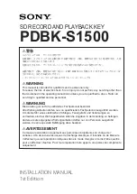
2. Insert both motors into the rectangular slots by keeping them an inclined positions before soldering. Make sure that the positive
motor pole marked with silver point being matched with the provided right positions of the BR001-1 board. After having soldered both
motor poles to the PCB, try to lay down the robot. The PCB should be in a parallel position to the floor. If not so, incline the PCB to be
parallel to the floor and then solder motor bodies to the PCB, as shown in Fig. 6.
3. Fix the battery holder to the circuit board with using two 6 mm. flat bolts as holders. Make sure that the wiring side facing the
right connecting point, as shown in Fig. 7.
4. Insert IDE port to the slot provided on the upper side of the PCB and solder it, as shown in Fig. 8.
5. The last step, assemble FK1105-1 board to the BR001-1 board one, as shown in Fig. 9.
http://www.futurekit.com
Figure 6 Motor Assembling To BR001-1 Board.
Figure 9
FK1105-1 And BR001-1 Boards Assembling
HIGH QUALITY ELECTRONIC KIT SET FOR HOBBY & EDUCATION
1
2
Figure 8 IDE Port Inserting.
Figure 5
Mini Caster Wheel
Fixing.
Figure 7 Battery Holder Fixing.
1
2
2
2
1
This soldering spot is
connecting with the both wire
of the battery holder
(red wire is positive pole
and black wire is negative pole).
1
3
Soldering the both side
of motor with PC-board.
Soldering the pin between the both
motor pole and PC-board
(positive pole make with silver point)
After having soldered both motor poles to
the PCB, try to lay down the robot.
The PCB should be in a parallel position
to the floor. If not so, incline the PCB to be
parallel to the floor and then solder motor
bodies to the PCB.
1
2