


Introduction:
Safety Information
Page 1 of 18 // email [email protected] tel: +44 (0) 1438 833577 fax: +44 (0) 1438 833565
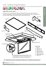
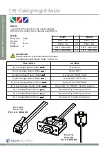
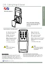
CHS - Ceiling Hinge & Swivel
Warnings:
1.
Read all technical instructions fully before installation and use. It is the installer’s responsibility to ensure that all
documentation is passed on the end user and read fully before operation.
2.
Keep all documentation.
3.
Heed all warnings.
4.
Follow all technical specifications and instructions during installation.
5.
Do not use near water unless the product has been specifically designed to do so.
6.
Clean only with a dry cloth.
7.
Do not defeat the purpose of the polarized or grounding type plug. A polarized plug has two blades, one wider
than the other. A grounding type plug has two blades and a grounding prong. The wide blade or third prong are
provided for your safety. If the provided plug does not fit your outlet, consult an electrician or contact the
manufacturer.
8.
Protect the power cord from being walked on or pinched, particularly at plugs, convenience receptacles, and the
point where the exit from the apparatus.
9.
Unplug the apparatus during lightning storms or when unused for long periods of time.
10.
Only use attachments/accessories specified by the manufacturer.
11.
Refer all servicing to qualified personnel. Servicing is required regularly on an annual basis, when the apparatus is
damaged in any way, liquid has been spilled or objects have fallen into the apparatus, the apparatus has been
exposed to rain or moisture, does not operate normally, or has been dropped.
12.
To completely disconnect the apparatus form the AC mains, disconnect the power cord plug from the AC
receptacle on the power control box.
13.
To prevent overheating, do not cover the apparatus. Install in accordance with the instructions.
14.
UK, Ireland and Hong Kong only – The power cord is supplied with a 13A plug having an earthing pin. The
apparatus is earthed and this pin is not required for safety, merely to operate the safety shutter of mains outlet.
15.
No naked flames such as lit candles should be placed on the unit.
16.
Observe and follow the local regulations when disposing of batteries.
17.
Do not expose the unit to dripping or splashing fluids.
18.
Do not place objects filled with liquid, such as vases, on the unit.
19.
Do not expose the batteries to excessive heat such as sunshine, fire or the like.
20.
For all mounted apparatus, the apparatus should be installed on solid wood, bricks, concrete or solid wood
columns and battens.
21.
Always turn off power at source before putting on or taking off parts and cleaning.
22.
Do not use outdoors unless marked for outdoor use.
23.
Exceeding the weight capacity can result in serious personal injury or damage to equipment.
Future Sound & Vision trading as Future Automation intend to make this and all documentation as accurate as possible. However, Future
Automation makes no claim that the information contained herein covers all details, conditions or variations, nor does it provide for every
possible contingency in connection with the installation or use of this product. The information contained in this document is subject to
change without prior notice or obligation of any kind. Future Automation makes no representation of warranty, expressed or implied,
regarding the information contained herein. Future Automation assumes no responsibility for accuracy, completeness or sufficiency of the
information contained in this document.
Safety Disclaimer
Important Safety Instructions
Explanation of graphical symbols
-(Electric Shock Symbol) = The lightning flash within an equilateral triangle is intended to alert you to the presence of un-insulated
“dangerous voltage” within the products enclosure that may be of sufficient magnitude to constitute an electric shock to persons
-(Caution Symbol) = The exclamation point within an equilateral triangle is intended to alert you to the presence of important
operating and maintenance (servicing) instructions in the literature accompanying the product
-(Tools Symbols) = The tools symbol within a coloured square are intended to highlight the required tools necessary for correct and
safe installation of the product. These are intended as a
guide only, and it is at the installer’s discretion as to which tools are used.
WARNING:
RISK OF ELECTRIC SHOCK, ONLY AUTHORIZED INSTALLERS TO OPEN THE POWER CONTROL BOX.
WARNING:
To reduce the risk of fire or electric shock, do not expose electrical parts to rain or moisture, unless the
product has been specifically designed to do so.
WARNING:
Failure to provide adequate structural strengthening, prior to installation can result in serious personal injury or damage to the
equipment. It is the installer’s responsibility to ensure the structure to which the component is affixed can support the four times the
weight of the component.
WARNING:
Do not exceed the weight capacity. This can result in serious personal injury or damage to the equipment. It is the installer’s
responsibility to ensure that the total combined weight of all attached components does not exceed that of the maximum figure stated.
WARNING:
Failure to provide adequate structural strength for this component can result in serious personal injury or damage to equip-
ment! It is the installer’s responsibility to make sure the structure to which this component is attached can support five times the combined
weight of all equipment. Reinforce the structure as required before installing the component.
Caution
Warning
Beware of
Moving Parts
Keep Hands
Clear
Danger
Electricity


