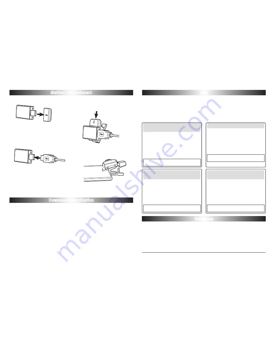
FUTABA TMA-1 Instruction Manual Download Page 2

OTG

 (USB On-The-Go) 

host cable

Cover

Cover

TMA-1

Clip holder

Tablet or smart phone

1. 

The cover of TMA-1 is removed. 

2.


Tablet or smart phone is connected with 

TMA-1 by an OTG (USB On-The-Go) host 

cable. 

3. 

TMA-1 is put in a clip holder and it is a 

tight fit. The cover is kept in the upper part 

of  clip holder. 

4. 

The TMA-1 insets into the tablet and or 

smart phone by using the the clip holder.

Method of attachment

Download of application

Link

Reference

1.

 With the tablet or smart phone that is to be use please open the Futaba WEB site.


www.futaba-rc.com

1.


First, a transmitter and a receiver are linked.

2. 

Transmitter is turned off. 

3. 

The link button of receiver is pushed for a long 

time to LED red/green blink.

4. 

The link button of TMA-1 is pushed for a long 

time to LED blink.
Completion of a link will change LED of TMA-1 

green from red only for a moment. 

1. 

The link button of TMA-1 is pushed for a long 

time to LED blink.

2.


The transmitter is turned on and set to Link 

mode.

+ button → MDL-SEL → LINK → Jog button push

3. 

Receiver is turned on. 

Completion of a link will change LED of TMA-1 

green from red.

1. 

The link button of TMA-1 is pushed for a long 

time to LED blink.

2. 

Transmitter is made into 

DISP mode

.


RX MODE → LINK


pushed for a long time.

3. 

The link button of receiver is pushed for a long 

time to LED blink.
Completion of a link will change LED of TMA-1 

green from red only for a moment. 

1. 

The link button of TMA-1 is pushed for a long 

time to LED blink.

2. 

The transmitter is turned on and set to Link mode.

Receiver → Link → Jog button push

3. 

The link button of receiver is pushed for a long 

time to LED blink.
Completion of a link will change LED of TMA-1 

green from red.

By linking the receiver and TMA-1, the data reception from a receiver becomes possible. 

"System Set"

 of TMA-1 is chosen from 

FASSTest

 or 

T-FHSS

. The receiver to be used is 

followed.  (

"System Set"

 is shown in the initial screen of TMA-1 application. )

● Before connecting the TMA-1 to either a tablet or smart phone make sure the transmitter 

and receiver are already linked when using 

FASSTest

. When using 

T-FHSS

 link all three 

simultaneous. 

FASSTest (T18MZ,T14SG,FX-22  

R7008SB,R7003SB)

T-FHSS Air (T10J  R3008SB)

T-FHSS Car (T4PLS,T4GRS  

R304SB,R304SB-E)

T-FHSS Car (T4PX 

R304SB,R304SB-E)

2.

 Select the tab of the file name TMA-1 application and download it.

3. 

Also download the manual of TMA-1 application.

*The tablet, smart phone, and cable to be used should use the elegance corresponding are OTC items. (A cable is less 

than 1 m) 

*Transmitter is not turned on when changing TMA-1 system by an application.
* When you link, the distance of TMA-1 and a receiver shall be less than 1 meter.
*The amount display of servo operations may change with transmitters.  


* T4PLS,T4GRS, make a sensor slot into default configuration. 


Slot 0

Receiver 


Slot 1

Temperature


Slot 2

RPM Sensor


Slot 6

Voltage Sensor 

* Don't use USB hub, when using TMA-1.

FUTABA CORPORATION

1080 Yabutsuka, Chosei-mura, Chosei-gun, Chiba-ken, 299-4395, Japan

Phone: +81 475 32 6982, Facsimile: +81 475 32 6983


©FUTABA CORPORATION     2014, 10   (1)

Summary of Contents for TMA-1

Page 1: ...er Telemetry sensor USB to electric supply is possible Dual core OS Android 3 2 Memory RAM 1GB ROM 16GB Internet connectivity Clip holder OTG USB On The Go host cable In Telemetry Receiver In Telemetry Sensor The selected Model TMA 1 Receiver and TMA 1 are made to link The power supply of TMA 1 is supplied from tablet or smart phone It has the same setup of a sensor slot number in the transmitter ...

Page 2: ... is pushed for a long time to LED blink 2 The transmitter is turned on and set to Link mode Receiver Link Jog button push 3 The link button of receiver is pushed for a long time to LED blink Completion of a link will change LED of TMA 1 green from red By linking the receiver and TMA 1 the data reception from a receiver becomes possible System Set of TMA 1 is chosen from FASSTest or T FHSS The rece...

Page 3: ... necessary to attach a sensor to the model according to the instruction manual of the telemetry sensor TMA 1 and telemetry receiver have to be linked according to the instruction manual a TMA 1 Turn OFF the Wi Fi function 2 4 GHz on the tablet or smart phone The display screen of this manual is an example of a tablet The display may change in part when a smart phone is used as compared to a tablet...

Page 4: ... tablet or smartphone Telemetry Receiver Option Telemetry Receiver Option SBS 01T SBS 01TE Temperature sensor SBS 01A Altitude sensor SBS 01RM Magnet type R P M sensor SBS 01RO Optical type R P M sensor SBS 01G GPS sensor SBS 01V Voltage sensor 2014 10 How to make TMA 1 app display that has telemetry sensor data on your tablet or smartphone The telemetry data such as altitude temperature and volta...

Page 5: ...ing Receiver Voltage Alert Temperature Setting Temperature Alert RPM Setting RPM Alert Altitude Setting Altitude Alert GPS Setting GPS Locus Setting Log 1 Start Data Logging 2 Check Log Data 3 Save Log Data Setting System Set Language About Table of contents 4 4 5 6 6 7 7 8 8 9 10 11 12 13 14 15 16 17 18 19 19 20 20 21 22 22 23 Start up TMA 1 ...

Page 6: ... Navigate to Setting About device Scroll to bottom Tap build number seven times You ll get a short pop up in the lower area of your display setting that you are now a developer 2 Enable USB Debugging How to call Developer Options with the tablet and smart phone to be used differs Please confirm by the tablet to be used or the manual of a smart phone Start up TMA 1 Visit Futaba WEB site www futaba ...

Page 7: ...een Tap Futaba TMA 1 icon Monitor Each telemetry sensor data can be displayed on the screen Log Record telemetry data System Set Select FASSTest or T FHSS in accordance with your radio system Monitor System Set Log ...

Page 8: ...streamlined approach see Page7 Signal level of the TMA 1 from a receiver can be checked by the signal level icon that is on the upper right of your screen It does not show the signal level from a transmitter to a receiver 1 Receiving Signal Level No signal Strong Weak Write Log ...

Page 9: ... Sensor Setting Add Page The title of the page can be changed as your preference Three kinds of display sizes can be chosen Tap Add Page Tap Tap Delete Page Deletion of the added page Write Log Page Title ...

Page 10: ...8 Sensor Setting Add a sensor on the page Delete a sensor from the page Initialize the page setting Long press button Servo Monitor Servo is chosen in device option ...

Page 11: ...n Setting Device Sensor or receiver voltage display item pushed for a long time this display will appear You can edit title name Select Sensor Select the sensor type Select sensor slot Select maximum value TMA 1 can display the receiver and external battery voltage ...

Page 12: ...age Alert High Low voltage alarm can be enabled with sound and red blink early screen Set receiver alarm Set external voltage alarm Set maximum value Set maximum value Set minimum value Set minimum value Alert Display ...

Page 13: ...e value of the temperature sensor Long press the button Setting Device Sensor or temperature display item pushed for a long time this display will appear You can edit title name Select Sensor Select Temperature Select maximum value Select the Unit or Select sensor slot ...

Page 14: ...12 Temperature Alert High Low temperature alarm can be enabled Alert Display Set Alarm Set maximum value Set minimum value ...

Page 15: ...nsor Long press the button Setting Device Sensor or RPM display item pushed for a long time this display will appear You can edit title name Select Sensor Select RPM Optics Number of fins Magnet Gear Ratio Select maximum value Select Types Optics or Magnet Select sensor slot ...

Page 16: ...14 RPM Alert High Low RPM alarm can be enabled Set Alarm Set maximum value Set minimum value Alert Display ...

Page 17: ...cordance with a transmitter it chooses the slot 1 5 8 13 16 21 24 29 Altitude is displayed TMA 1 can display Altitude sensor Long press the button Setting Device Sensor or Altitude display item pushed for a long time this display will appear You can edit title name Select Sensor Altitude is chosen Select altitude unit you can select either m or ft Select variometer unit you can select either m s o...

Page 18: ...16 Altitude Alert High Low altitude alarm can be enabled Alert Display Set Alarm Set maximum value Set minimum value ...

Page 19: ...n accordance with a transmitter it chooses the slot 8 16 24 GPS is displayed TMA 1 can display the GPS sensor Long press the button Setting Device Sensor or GPS display item pushed for a long time this display will appear You can edit title name Select Sensor GPS is chosen Select variometer unit you can select either m s or mph Select speed unit you can select either km h or m h ...

Page 20: ... course of the model to be sure the model stays on that course Zoom in Two dimensional Long press the button Setting Device Sensor or GPS Locus display item pushed for a long time this display will appear You can edit title name Sensor is chosen Select GPS Locus In accordance with a transmitter it chooses the slot 8 16 24 ...

Page 21: ...19 Log TMA 1 can take and save sensor log data as text data 1 Start Data Logging Tap this button to start data logging Tap this button again to stop the data logging ...

Page 22: ... Log Log data is stored on the folder Internal storage TMA_1 Log of the tablet smart phone 2 Check Log Data 3 Save Log Data If a sensor is chosen Log data can see The data sorted by data Tap Log button on the initial screen ...

Page 23: ...ystem reset the TMA 1 2 Turn OFF the receiver and transmitter before switching the transmission system FASSTest or T FHSS Error message Please confirm link or restart link device Start by selecting either a tablet or smart phone 1 Note Tap the System Set button on the screen TMA 1 and a tablet smart phone are connected System Set Success Error ...

Page 24: ...uage This system supports two languages English and Japanese You can select the language English or Japanese by using the language bar in tablet or phone About Tap the About button to find the software version ...

Page 25: ...een mode alert sound and defaults can be set in this system FUTABA CORPORATION 1080 Yabutsuka Chosei mura Chosei gun Chiba ken 299 4395 Japan Phone 81 475 32 6982 Facsimile 81 475 32 6983 FUTABA CORPORATION 2014 10 1 ...

Reviews: