

Adjustments
Flight Adjustments
AVCS / NORMAL Mode
● A trimmer's operation
*
Since the trimmer is small and delicate, operate
it by gently using the provided mini screwdriver.
6HWXSEHIRUHDÀLJKW>5HPRWHJDLQXVH@
Adjusting gain with the transmitter.
When S.BUS connection or the gyro gain CH of the port 2 of a
gyro and a receiver is connected.
1
Set the servo selection switch to the setting for your tail rotor
servo. See chart below.
2
Set up your transmitter by following the directions in the
manual. Gyro gain is set up to 50% by AVCS. Please refer to
the graph, AVCS, NORMAL or when unclear. It judges by the
LED on the GY440. AVCS: Red NORMAL: Green
3
Receiver ON → The GY440 requires 3-5 seconds to initialize
when the power is turned on. Do not move the helicopter and
do not move the
rudder
stick during this initialization or the
gyro may not initialize properly. Once the initialization process
has been completed the
rudder
servo will move (a little)
several times indicating that the GY440 is now ready for flight.
If the neutral has shifted, LED will blink orange. In that case, it
reboots.
4
Move the rudder stick to the left and right and make adjustments
with the limit trimmer. Adjust for maximum travel, making sure the
servo horn doesn't hit the linkage.
>5HPRWHJDLQQRWXVH@
Adjusting gain with the GY440 trimmer.
When not using an S.BUS connection and port 2 is not connected.
In this case, a limit trimmer is automatically changed by the gyro
JDLQVHWWLQJWULPPHU$OLPLWLV¿[HGE\GHJUHHVRIULJKWDQG
left.
Adjust the transmitter and gyro while repeatedly taking off and
landing and with the aircraft on the ground.
7UDQVPLWWHUDGMXVWPHQWVPXVWQRWEHPDGHZKLOHÀ\LQJ
because it is dangerous.
1
Set the sensitivity to the position at which hunting does not
occur during hovering and flight.
2
Adjust the hovering and flight rudder effect using the
transmitter's D/R or AFR function.
* Do not adjust with the End Point (ATV) function. If the End Point (ATV)
IXQFWLRQLVXVHGWULPPLQJPD\FKDQJH
AVCS 100%
NORMAL 100%
NORMAL 50%
LIMIT
GAIN
0%
AVCS 50%
<
A gain trimmer's work
>
<
GAIN CH
>
Operation in AVCS mode
If the rudder stick is operated or the helicopter is moved when the
helicopter was stopped during operation in the AVCS mode, the servo
will not return to the neutral position even if the rudder stick is re-
turned to the neutral position, and when the rudder stick is moved, the
rudder servo controls operation until the tail reaches the maximum
point. This is caused by addition of an integration function as an
$9&6PRGHRSHUDWLRQDQGLVQRWDQDEQRUPDOLW\,QDFWXDOÀLJKWWKH
gyro constantly monitors movement of the tail and controls the servo
so that movement of the tail is stopped.
AVCS mode servo neutral position check method;
If the rudder stick or the helicopter was moved in the AVCS mode, the servo
will not return to its original neutral position. When the power is turned on,
the servo will return to the neutral position. The servo neutral position can
also be checked by the following method.
Neutral
position
Move the rudder stick 3 times to its full stroke to the left
and check method right at an internal of within 1 second
and immediately return the rudder stick to the neutral
position. The servo moves to the neutral position about 1
second later.
NORMAL mode sends control signals to the rudder servo only
when the tail of the helicopter moves. When the tail stops mov-
ing, the control signal from the gyro becomes zero. Conversely,
the AVCS mode continues to send control signals to the servo
even when the tail of the helicopter stops moving. The following
sequentially describes the NORMAL mode and the AVCS mode.
2SHUDWLRQRI1250$/PRGH
%DVLFRSHUDWLRQLVGHVFULEHGE\FRQVLGHULQJWKHFDVHZKHQWKH
helicopter is hovering under cross-wind conditions. With a nor-
PDO PRGH ZKHQ WKH KHOLFRSWHU HQFRXQWHUV D FURVVZLQG WKH
force of the cross-wind causes the tail of the helicopter to drift.
:KHQWKHWDLOGULIWVWKHJ\URJHQHUDWHVDFRQWUROVLJQDOWKDWVWRSV
WKHGULIW:KHQWKHWDLOVWRSVGULIWLQJWKHFRQWUROVLJQDOIURPWKH
gyro becomes zero. If the cross-wind continues to cause the tail
WRGULIWLQWKLVVWDWHWKHVWRSRSHUDWLRQLVUHSHDWHGXQWLOWKHWDLO
IDFHVLQWRWKHZLQGV7KLVLVFDOOHGWKHZHDWKHUYDQHHIIHFW
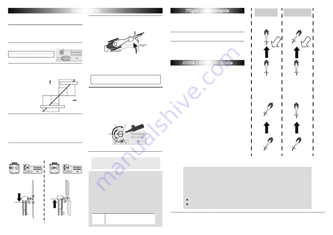
Operation of AVCS mode
&RQYHUVHO\ZLWKDQ$9&6PRGHZKHQWKHKHOLFRSWHUHQFRXQ
-
WHUVDFURVVZLQGDQGWKHWDLOGULIWVDFRQWUROVLJQDOIURPWKHJ\UR
VWRSVWKHGULIW$WWKHVDPHWLPHWKHJ\URFRPSXWHVWKHGULIWDQ
-
gle and constantly outputs a control signal that resists the cross-
ZLQG7KHUHIRUHGULIWLQJRIWKHWDLOFDQEHVWRSSHGHYHQLIWKH
FURVVZLQGFRQWLQXHVWRHIIHFWWKHKHOLFRSWHU,QRWKHUZRUGVWKH
gyro itself automatically corrects(auto trim) changes in helicopter
WDLOWULPE\FURVVZLQG&RQVLGHULQJRSHUDWLRQRIDQ$9&6PRGH
ZKHQWKHWDLORIWKHKHOLFRSWHUURWDWHVWKHVHUYRDOVRURWDWHVLQ
accordance with the angle of rotation of the tail. When the tail
VWRSVURWDWLQJWKHVHUYRMXGJHVWKDWLWKDVVWRSSHGLQWKDWSRVL
-
tion. This is the auto trim function.
In
AVCS
operation
mode
In
NORMAL
operation
mode
Hovering in a cross wind.
The tail will drift.
AVCS
is working
properly during
a cross wind.
If it starts right drift
If it starts right drift
A head turns to a
direction of movement
automatically.
If no left rudder input
is given, the machine
will drift to the right.
Cross
wind
Cross
wind
Hovering
High-speed flight
0%
-50%
+50%
50%
50%
100%
100%
+100%
-100%
End point rate
Gain
NORMAL side(LED : GREEN)
AVCS side(LED : RED)
Please take a look at both the directions for the helicopter as well
as the transmitter.
LIMIT
GAIN
LIMIT
GAIN
Hold the rudder
stick full left.
Adjust the left limit
with the trim.
Hold the rudder
stick full right.
Adjust the
right
limit with the trim.
Adjust the linkage set
up to get the
maximum throw.
Adjust the linkage set
up to get the
maximum throw.
Bottom view of the
tail section with the
rudder stick full left.
Bottom view of the
tail section with the
rudder stick full right.
【
Adjustment at the limit trimmer
】
【
Preflight check
】
Helicopter is turned to the Left
⇒
Rudder operates on the
Right.
*This check is performed in the state where an engine (motor)
never starting.
5
If the rudder servo moves to the Right when the nose of the
helicopter moves to the Left, the gyro direction is correct. If
the rudder servo moves to the Left, switch the direction using
the
Gyro Direction Switch
.
,I\RXWU\WRIO\WKHKHOLFRSWHUZKLOHWKHJ\URGLUHFWLRQLVLQFRUUHFW
ZKHQWKHURWRUURWDWHVFORFNZLVHWKHKHOLFRSWHUQRVHZLOO\DZWRWKH
Left and cause an extremely dangerous situation.
First, we suggest to start with AVCS set to 50%.
FUTABA CORPORATION
1080 Yabutsuka, Chosei-mura, Chosei-gun, Chiba-ken, 299-4395, Japan
Phone: +81 475 32 6982, Facsimile: +81 475 32 6983
)87$%$&25325$7,21
What is S.BUS?
Unlike conventional radio systems, the
S.BUS
system uses
data communication to transmit control signals from a
receiver to a servo, gyro, or other
S.BUS
compatible device.
This data includes commands such as “move the channel 3
servo to 15 degrees, move the channel 5 servo to 30 degrees”
to multiple devices. The
S.BUS
devices execute only those
commands for their own set channel. For this reason, it can
be used by connecting multiple servos to the same signal
line.
* Set the channel at the
S.BUS
servos by using an
SBC-1
channel changer or a
CIU-2
USB serial interface.
*
&DQDOVREHXVHGWRJHWKHUZLWKFRQYHQWLRQDRZHYHUFRQYHQWLRQDOVHUYRVFDQQRWEHXVHGE\WKH
S.BUS
output.
*
:KHQXVLQJVHUYRVZLWKDUHPRWHEDWWHU\SDFNXVH
S.BUS
+XEZLWK&DEOHZD\UHPRWHEDWWHU\SDFNXVH
Please refer to the instruction manual of
S.BUS
+XEZLWK&DEOHZD\UHPRWHEDWWHU\SDFNXVHIRUWKHFRQQHFWLRQPHWKRG
3OHDVHWXUQRQWKHSRZHUVXSSO\RIWKHWUDQVPLWWHU¿UVWZLWKRXWIDLODQGQH[WWXUQRQWKHUHFHLYHULI\RXXVH
S.BUS
0RUHRYHUSOHDVHXVHLW
DIWHULWFRQ¿UPVWKHRSHUDWLRQZLWKRXWIDLO2WKHUZLVHWKH
S.BUS
communication cannot be judged and it is likely to malfunction.
The wiring for the
S. BUS
VHUYRLVUHSODFHGDWSRZHUVXSSO\2)),I\RXUHSODFHWKHZLULQJLQSRZHUVXSSO\21
S. BUS
communications
FDQQRWEHMXGJHGDQGLWVHHPVWRPDOIXQFWLRQ
S
imilarly the procedure of
1.3.7
is followed.
LIMIT
GAIN
1520uS:
BLS254, BLS257, S9254, S9257,etc.
760uS:
BLS256HV,BLS251, S9256, S9251