when desiring to make the spin and other steering
angles large, set it to ON and adjust the horn, ad-
justers, and trimmers for level flight.
When the dual travel switch is set to OFF, kick
up is set, and the steering angle becomes large.
•Aileron, elevator, and rudder right and left (UP.
DOWN) angle adjustment
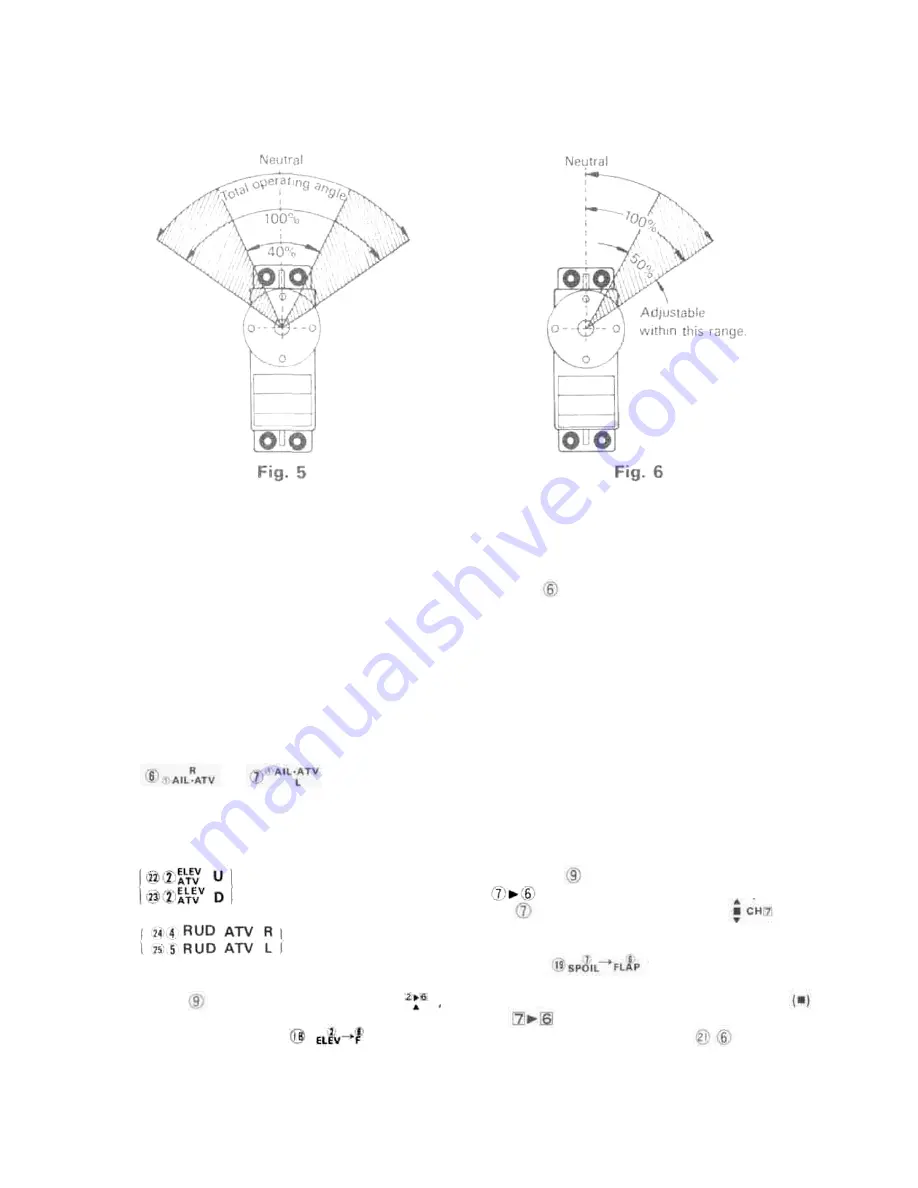
[ATV (Adjustable Travel Volume)]
The aileron, elevator, and rudder steering angles
can be made small within the range of the hatched
lines in Fig. 6.
When the aileron right roll and left roll rates are
different, they can be made the same by adjusting
the and trimmers of Fig. 2.
This also applies to the elevator and rudder. An
elevator UP and DOWN difference can also be
provided for easier flying.
The elevator ATV trimmers are
point, linkage is extremely simple.
Dual travel is operative even at elevator and flap
mixing.
Use the CH6 flap trim lever of Fig. 1 to adjust
the flap neutral position. Use this trimmer is the
same manner as a trim lever (aileron trim and
elevator trim).
Mixing is released when the MIX switch is set to
the center position (• mark). The flap neutral
position is not changed at this time.
(NOTE) Channel 6 is for the flaps, but can also be
used as a spare channel. However, since the
travel range is slightly narrow, adjust the
linkage.
•Adjustment when mixing spoiler, etc. and flaps
(When using the flaps and spoiler as an air brake)
Connect the flap servo to channel 6 of the re-
ceiver and the spoiler servo to channel 7.
of Fig. 2.
The rudder ATV trimmers are
of Fig. 2.
•Elevator and flap mixing adjustment
Connect the flap servo to channel 6 of the receiver.
When the MIX switch of Fig. 1 is set to
the elevator and flaps are mixed. Set the steering
When the MIX switch of Fig. 1 is set to
. the spoiler is mixed with the flaps. When
the CH7 switch of Fig. 1 is set to , the
spoiler and flaps are operated simultaneously.
The amount of mixing at this time is adjusted
with the trimmer of Fig. 2.
The direction and amount can also be set.
When the MIX switch is set from RELEASE
to , the flap neutral position may deviate.
If this occurs, adjust the NEUTRAL
trimmer of Fig. 2 so that the flap neutral position
does not change when the MIX switch is set to
any position.
Summary of Contents for FP-8JN
Page 1: ...Futaba DIGITAL PROPORTIONAL RADIO CONTROL ...
Page 5: ... TRANSMITTER CONTROLS Fig 1 ...
Page 11: ... USING THE RECEIVER SERVOS Aileron servo ...
Page 16: ......


