background image

16

Model name function

Assign a name to the model memory. By giving each model a name that is immediately recognizable, you can quickly select 
the correct model, and minimize the chance of flying wrong model memory that could lead crash.

To assign a name

1. Access the Model Select function in the programming mode (by pressing the MODE and 

SELECT keys simultaneously and holding them down for one second). To select the model 
number you wish to change press the DATA INPUT lever and hold it down for 0.5 seconds 
until the desired model number appears..

2. Push SELECT key five times after seeing on the screen the model memory where you want 

to set the model name, then you will see the model name on the screen.  

3. Choose a character for the first digit by using DATA INPUT lever. Then move to the next digit 

by pressing the SELECT key and choose a character in the same way. Continue choosing 
characters for the third and fourth digits. You can use up to four characters for the name.

REVR   Servo Reversing 

The servo reversing function is used to change the direction that a servo responds to a control input from the transmitter 
(stick or switch). After using the reversing function, check 

all

 the controls on the model to 

be certain

 they are operating in the 

correct direction and that you did not inadvertently reverse a servo other than the one intended. Reversing the wrong servo (and 
not checking the response of the controls before each flight) may be the most common cause of a crash! 

To reverse a servo: 

1. Enter the programming mode and use the MODE key to access the 

REVR

 function. 

2. Use the SELECT key to select the channel you wish to reverse. 

3. Push the DATA INPUT lever downward for 0.5 seconds to reverse the servo (REV), or push 

the lever upward for 0.5 seconds to make the servo operate normally (NOR). The arrow will 
indicate the condition of the servo (normal or reversed). 

4. Use the SELECT key to display other channels to be reversed. 

Dual Rates / Exponential Settings

The aileron, elevator and rudder dual rates on the 6EXHP are simultaneously activated by the dual rate switch. The amount of 
travel decrease for each control may be set between 0% and 100% of the values set for the end points (explained in End Point 
Adjustment on page 17). 

Note

: It is possible to set a dual rate value to zero, thus causing no response from that channel. If the dual rates are 

inadvertently set to zero, a crash could result.

Note

: When performing initial model setup, the E.P.A.s should be set 

prior to

 setting the dual rates. When setting the E.P.A.s 

for the first time on a new model, the dual rates should be set to 100%.

D/R   Dual Rate Settings

To set the dual rates: 

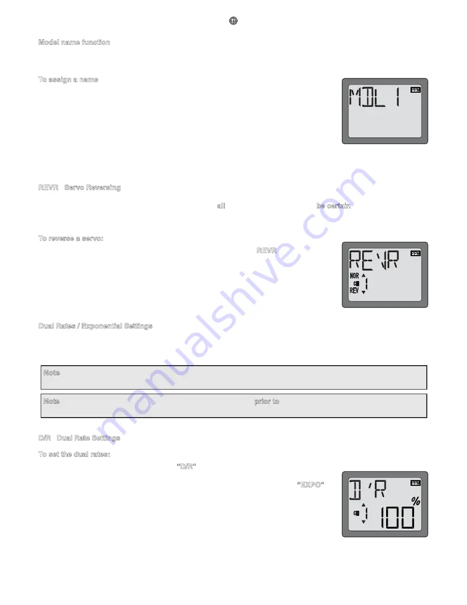
1. Enter the programming mode. Access the 

“D/R”

 screen with the MODE key. 

2. Select the channel to be adjusted (1-aileron, 2-elevator, 4-rudder) by pressing the SELECT 

key until the desired channel number the left side on the screen. Note: If a 

“EXPO”

 will 

appear on the screen, you have pressed the SELECT key too many times and displayed 
the values for the exponentials (explained later). Press the SELECT key to return to the dual 
rate values. 

3. Place the dual rate switch in the desired position for the value you wish to change. (Generally, 

pilots prefer to have the switch in the “up” position for the high rate, and in the “down” 
position for the low rate.) 

4. Change the dual rate value using the DATA INPUT lever until the desired control throw is achieved. If you wish to change 

the control throw when the switch is in the other position as well, flip the switch, then use the DATA INPUT lever to change 

Summary of Contents for 6EXP

Page 1: ...MUNUAL for Futaba 6EXP 6 channel PCM PPM FM selectable Radio control system for Airplane helicopter 1M23N12013 Futaba Corporation Technical updates available at http www futaba rc com Entire Contents...

Page 2: ...nt Adjustments 17 TRIM Trim Settings 18 FS Fail safe PCM mode only 30 ACRO functions PMX1 Programmable Mixer 1 19 PMX2 Programmable Mixer 2 19 FLPR Flaperon mixing 20 FLTR Flap trim 20 V TL V tail mix...

Page 3: ...y also refer to your hobby dealer or contact the Futaba Service Center at the web site fax number or telephone number below www futaba rc com Fax 217 398 7721 Telephone 8 00 am to 5 00 pm Central time...

Page 4: ...the R156F we cannot recommend its use in other types of models gas powered models etc that are own at longer distances Receiver R146iP R146iP narrow band PCM6 channel mini receiver Receiving on 29 35...

Page 5: ...ssed in inches or millimeters The model in the diagram has 1 2 13mm of up elevator throw Throw can also refer to the distance a servo arm or wheel travels Dual rate D R On the 6EXP the dual rate switc...

Page 6: ...can be set with Futaba GY401 502 611 Gyro on gyro function of this transmitter Programming features include servo reversing and E P A on all channels dual rates exponentials throttle curve pitch curv...

Page 7: ...ns SELECT key Used to display the values for the current function Throttle cut button To use the throttle cut function lower the throttle stick all the way then push the throttle cut button to fully c...

Page 8: ...trims on the transmitter then find the arm that will be perpendicular to the pushrod when placed on the servo After the servos are installed operate each servo over its full travel and check that the...

Page 9: ...ng hole Rubber grommet or silicon tube etc Antenna Nonmetal tube Please use rubber grommet or silicon tube to protect from cut or peel off insulation of antenna on the fuselage antenna exiting hole Pl...

Page 10: ...ored red goes into the receiver Receiver on off switch the plug colored red goes into the receiver Receiver Switch Harness To Battery Charging Jack Black Aileron Servo CH1 Optional Gyro System Elevato...

Page 11: ...llow the manufacturer s instructions provided with the charger so you do not overcharge the batteries NEVER charge the batteries at a rate higher than 1 000mAh The batteries should also be discharged...

Page 12: ...nd SELECT keys only determine what will be displayed on the screen and will not change any of the settings Only when using the DATA INPUT lever will you be able to change any of the settings Model nam...

Page 13: ...ts Land as soon as safely possible 8 5 Volts Emergency Land immediately Mixer alert warning The Mixer alert warning is displayed to alert you whenever you turn on the transmitter with any of the mixin...

Page 14: ...Access the Model Select function in the programming mode by pressing the MODE and SELECT keys simultaneously and holding them down for one second The number for the current active model will be blinki...

Page 15: ...ode Modulation To select modulation 1 Access the Model Select function in the programming mode by pressing the MODE and SELECT keys simultaneously and holding them down for one second To select the mo...

Page 16: ...ver downward for 0 5 seconds to reverse the servo REV or push the lever upward for 0 5 seconds to make the servo operate normally NOR The arrow will indicate the condition of the servo normal or rever...

Page 17: ...ual rates the end points should be set prior to setting the dual rates If you set the dual rates rst and then go back and change the end points the dual rate throws will also change The EPA function i...

Page 18: ...4 Connect the pushrods to the control surfaces Adjust the length of the pushrods until the control surfaces are centered when the servos are centered Note The throttle trim affects the throttle servo...

Page 19: ...S Master mixing Then select the channel by pushing DATA INPUT lever Channel 1 aileron in this gure is assigned to the master 4 Push SELECT key to call the screen for selecting channels to control SLV...

Page 20: ...n order to enable Flaperon mixing you rst need to cancel Elevon mixing However it is allowed to use Flaperon and V Tail mixing simultaneously 3 Push the DATA INPUT lever upward for 0 5 seconds This wi...

Page 21: ...ing allows the ruddervators to operate both as rudders and elevators The same as the other mixes V tail mixing requires that each ruddervator be operated by a separate servo To activate V tail mixing...

Page 22: ...necessary use the Servo Reversing function to achieve the correct direction of servo throws Intended for tailless ying wing models such as delta wings and ying wings elevon mixing mixes channel 1 aile...

Page 23: ...INPUT lever to set the percentage of elevator travel rate from 100 to 100 5 Next you set the right wing to channel 2 elevator setting Press the SELECT key to display the CH2 and ashing sign Use the D...

Page 24: ...g Use this function together with the normal throttle curve so that up down control has a constant engine speed To set the normal pitch curve 1 Enter the programming mode and use the MODE key to acces...

Page 25: ...ion is not activated When you set I PI function you must activates I TH function 3 Use SELECT key to select the desire curve point Point 1 is shown initially which is throttles stick all the way downw...

Page 26: ...no input was given and will correct for it How does it help in helicopter setup A good gyro will totally eliminate the need for revo mixing The gyro will sense and correct the unwanted motion for you...

Page 27: ...er the programming mode and use the MODE key to access the GYRO function 4 Push the DATA INPUT lever upward for 0 5 seconds This will cause the flashing INH display to change to a ashing ON display No...

Page 28: ...vator to throttle mixing rate from 0 to 50 SWSH Swashplate types selection Swash AFR HELI only This function can chose from three swashplate types Swash AFR can be set if you chose 3 S or 3 E type 1 S...

Page 29: ...ith the model Basically EPA see page17 is set near 100 with these three servos To set the servo reveres function see page16 so that swashplate keeps horizontally and moves correct direction up and dow...

Page 30: ...s happens you should immediately land If you need to increase throttle for your landing approach you may temporarily reset the failsafe function by moving the throttle stick to idle after which you ll...

Page 31: ...at Startup To enter or leave Programming Mode press MODE and SELECT keys simultaneously for one second To change the Stick Mode turn on the transmitter holding MODE and SELECT keys down simultaneousl...

Page 32: ...W CHART HELI MODE FUNCTIONS Screen at Startup To enter or leave Programming Mode press MODE and SELECT keys simultaneously for one second To change the Stick Mode turn on the transmitter holding MODE...

Page 33: ...rims of the student s radio to match that of the instructor s 7 Turn on the receiver switch in the model Depress the trainer switch on the instructor s radio Use the student s radio to operate the con...

Page 34: ...l If you must y in wet weather during a contest be sure to cover the transmitter with a plastic bag or other waterproof cover cademy of Model Aeronautics 5151 East Memorial Drive Muncie IN 47302 9252...

Page 35: ...rformed before the rst ight of a new model It is not necessary to do a range check before every ight but is not a bad idea to perform a range check before the rst ight of each day A range check is the...

Page 36: ...il Elevon INH ON FLPR INH ON V TL INH ON ELVN INH ON Master Ch Ailerons differential rate Slave Ch Rate Sw CH 2 Elevator rate CH 4 Rudder rate CH 1 Aileron rate CH 2 Elevator rate PMX2 Programmable Mi...

Page 37: ...N R N R N R N R N R MIXING SETTING N TH NormalThrottle Curves Normal Pitch Curves Idle UPThrottle Curves Idle UP Pitch Curves N PI I TH INH ON I PI Throttle Hold HOLD Pitch Rudder Mixing REVO Gyro Mi...

Reviews: