background image

Chapter 1: Operational Overview

1-2

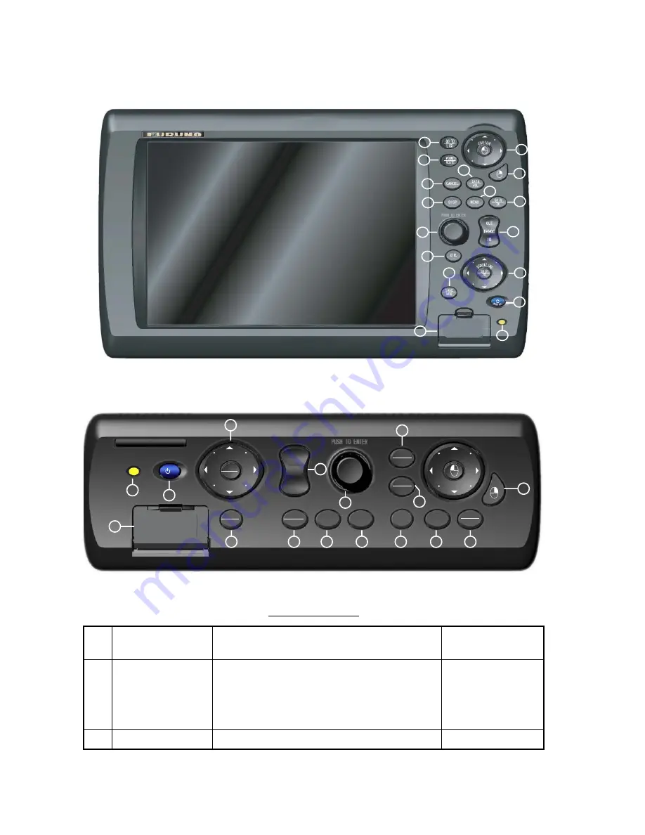
Control Description

The controls of your unit are shown in the figure below. Controls are backlit for easy 
viewing in nighttime use.

DIsplay Control Unit (DCU12)

 Control unit (MCU-001)

Control description

No.

Label

Function

Key on PC or 

control on mouse

1

POWER

Momentary press: 

Turn on the power; adjust 

key dimmer when equipment is active. On the 
DCU12 it additionally functions to adjust display 
brilliance.

Long press: 

Turn the power on/off 

F13

2

Card drive

Card drive for chart cards and memory cards.

None

1

2

3

4

5

6

7

8

9

10

11

12

13

14

15

16

17

10

5

9

CTRL

CANCEL

MENU

POINTS

SAVE

MOB

DISP

GO TO

LIST

DATA

VOL

SHIP

3D

SCR

OLLI NG

GAIN

TX

ROUTE

CURSOR

2

3

14

7

4

12

13

6

11

8

OUT

RANGE

IN

15

16

1

17

5

9

Summary of Contents for NAVNET 3D MFDBB

Page 1: ...www furuno co jp MFDBB Multi Function Display ...

Page 2: ...s shown in this manual may not match the screens you see on your display The screen you see depends on your system configuration and equipment settings Store this manual in a convenient place for future reference FURUNO will assume no responsibility for the damage caused by improper use or modification of the equipment including software by an unauthorized agent or a third party When it is time to...

Page 3: ...ergy which can be harmful particularly to your eyes Never look directly into the antenna aperture from a close distance while the radar is in operation or expose yourself to the transmitting antenna at a close distance Radiation hazard figures TBA at later time Do not open the equipment Only qualified personnel should work inside the equipment Make sure no is near the antenna unit before turning o...

Page 4: ...is useful as an anti collision aid However it does not remove the require ment for maintaining a vigilant watch Always maintain a vigilant watch while underway Do not leave ropes or other objects in the vicinity of the antenna unit Fire electrical shock or injury can result if an object becomes entangled in the antenna unit Use the correct fuse Use of an incorrect fuse can cause fire or serious da...

Page 5: ...Safety Instructions iv This page is intentionally left blank ...

Page 6: ... Moving the Cursor 1 9 Status Bar 1 9 ROTOkeys 1 10 Context Sensitive Pop up Menus 1 11 NavData 1 12 1 9 Menu Overview 1 13 1 10 Man Overboard MOB Function 1 16 1 11 Selecting Language Boat Characteristics 1 17 Selecting Language 1 17 Setting Your Boat s Characteristics 1 17 1 12 Entertainment 1 18 Chapter 2 Chart Plotter Operation 2 1 2 1 Chart Cards 2 1 2 2 Selecting Chart Type 2 1 2 3 Selecting...

Page 7: ...te Follow Options 2 27 Route Log 2 29 Reviewing Passage Plan 2 30 Editing a Route On screen 2 32 Finding a Route on a Map 2 33 Renaming a Route 2 33 Merging Two Routes 2 33 Deleting Routes 2 34 Globally Showing Hiding Routes 2 35 2 14 Working With Track 2 36 Turning the Track Display On Off 2 36 Track Thickness 2 36 Track Color 2 37 Clearing Current Track 2 37 Saving Current Track 2 38 Replaying S...

Page 8: ...uard Zone 3 16 Enabling Disabling Audio Alarm 3 16 3 12 Proximity Target Alarm 3 16 3 13 Watchman 3 17 3 14 Echo Trails 3 17 3 15 Echo Stretch 3 18 3 16 Echo Average 3 18 3 17 Automatic Offcenter 3 19 Setting Auto Offcenter Speed 3 19 Enabling Disabling Auto Offcenter 3 19 3 18 Wiper 3 19 3 19 Echo Color 3 20 3 20 Background Color 3 20 3 21 Displaying Own Ship Icon 3 21 3 22 Radar Overlay Automati...

Page 9: ...Loading Data 6 3 Deleting Files 6 3 Moving Files 6 3 Manage Chart Catalog 6 3 Request Update File 6 3 Load Update File 6 3 Chapter 7 Customizing Your Unit 7 1 7 1 ROTOkeys 7 2 Selecting the ROTOkey Set to Use 7 4 Customizing the ROTOkeys 7 5 7 2 NavData 7 7 7 3 Changing Display Arrangements 7 10 7 4 Chart Setup 7 12 Mapmedia Sub Menu 7 12 S52 Sub Menu 7 12 C Map Sub Menu 7 13 7 5 General Menu 7 14...

Page 10: ...ng 8 3 Radar Troubleshooting 8 3 Chart Plotter Troubleshooting 8 4 8 6 Diagnostic Wizard 8 4 Memory Test 8 4 Keyboard Test 8 5 I O Test 8 5 BBGPS Test 8 5 Radar ARPA Test 8 5 8 7 GPS Status Display 8 5 8 8 Restoring Default Settings 8 6 Specifications SP 1 Index IN 1 ...

Page 11: ...Table of Contents x This page intentionally left blank ...

Page 12: ...asing FURUNO equipment Features The all new NavNet 3D series of multi function displays combine radar chart plotter AIS receiver etc into an easy to use networked navigation system A high quality fog less color LCD presents navigation data chart radar echoes etc in vivid colors Use of a commercial monitor is also possible Chart plotter radar navigation data etc are instantly transferred between Na...

Page 13: ...lays with connection of applicable sensors Steering Engine Weather Wind TIde Multimedia To be developed Weather information display option available with connection of 3D display of chart receiver or MaxSea s chopper interface Sensor data commonly shared with all units connected via Ethernet IP camera connectable to monitor onboard activity NMEA 2000 interface for connection of VHF receiver GPS re...

Page 14: ... IN MICROPHONE DISPLAY CONTROL UNIT DCU12 CONTROL UNIT MCU 001 AND OR2 HUB GPS NAVIGATOR GP 320B AIS RECEIVER HEADING SENSOR or EXTERNAL BUZZER USB DEVICE MOUSE KYBD NMEA 2000 SENSOR ETC POWER SUPPLY UNIT PSU 0131 Standard Supply Optional Supply Local Supply 1 For 25 kW radar sensor 2 Max two units total PROCESSOR UNIT MPU 001 FISH FINDER DFF1 ETR 6 10N ETR 30N under development 100 110 220 230 VA...

Page 15: ...System Configuration xiv This page is intentionally left blank ...

Page 16: ...re identical except for the POWER switch on the DCU12 it also func tions to adjust display brilliance Discrete keys whose key labels have two text labels separated by an underline carry two functions The top label is the main function and the bottom label the secondary function You access those functions with a short push and long push respectively You operate the chart plotter radar etc with a co...

Page 17: ...ntrol on mouse 1 POWER Momentary press Turn on the power adjust key dimmer when equipment is active On the DCU12 it additionally functions to adjust display brilliance Long press Turn the power on off F13 2 Card drive Card drive for chart cards and memory cards None 1 2 3 4 5 6 7 8 9 10 11 12 13 14 15 16 17 10 5 9 CTRL CANCEL MENU POINTS SAVE MOB DISP GO TO LIST DATA VOL SHIP 3D SCRO LLI N G GAIN ...

Page 18: ...osition as waypoint LIST long push Open route building tool F8 10 Cursorpad Pad Shift cursor Like the click button on a PC mouse Hereafter referred to as left button key Drag mouse Left mouse button 11 Right button key Show erase pop up menu Hereafter referred to as right button key Right mouse button 12 DATA VOL DATA short push Show hide NavData VOL long push Change audio level F7 13 MENU Open cl...

Page 19: ...tly 3 Close the lid You will hear a click when the lid is correctly closed Removing a Chart Card 1 Open the card drive lid 2 Push in the card The card will pop half way out Pull out the card 3 Close the lid You will hear a click when the lid is correctly closed Precautions with Chart Cards Do not remove a card while the chart is being drawn This can cause the equipment to freeze Do not insert or r...

Page 20: ...oot program nos for the MCU 001 and or DCU12 are shown 1 4 Adjusting Display Brilliance Key Dimmer The brilliance of the DCU12 s display can be adjusted with the POWER BRILL key 1 Push the POWER BRILL key to display the LCD brilliance and key dimmer adjust ment window 2 Rotate the Rotary Knob to select the item you wish to adjust and push the Rotary Knob 3 Rotate the Rotary Knob to adjust item sel...

Page 21: ...ndow The labels in the illus tration below do not appear on the actual display Display selection window 2 Rotate the Rotary Knob to place the display desired inside the on screen display unit 3 Push the Rotary Knob to confirm selection Switching Active Display in Combination Displays Use the CTRL key to switch active display in combination displays Each time the key is operated the active display ...

Page 22: ... marked on screen with a boat icon the configuration of which can be selected from the menu If no head ing or course data is available your boat is shown as a hollow circle flashing Waypoints and routes you have entered are shown on the display and they can easily be moved deleted and edited from a pop up menu In addition to waypoint and route processing the chart plotter also provides informa tio...

Page 23: ... relative to own ship True motion shows own ship and other moving objects moving in accor dance with their true courses and speed Dual VRMs are provided to measure the range to objects and dual EBLs to measure the bearing to targets A guard zone can be created to be alerted to targets in a spe cific area The trail of targets can be shown in afterglow to monitor their movement Range range ring inte...

Page 24: ...om of the screen if it is displayed Cursor position box Status Bar The status bar is the yellow horizontal bar at the top of the display It provides operat ing information with text messages and sensor status with icons Text operational help alarm alert etc runs across the text message area from right to left tickertape style When an alarm is violated the bar turns red and the name of the offendin...

Page 25: ...e or push the Rotary Knob to show the ROTOkeys Long push the knob to show the standard keys These keys can also be activated when the basic keys are shown In the example below a few of the basic ROTOkeys for the chart plotter are shown Basic ROTOkeys for chart plotter 2 Rotate the Rotary Knob to select the ROTOkey you wish to use As you step through the ROTOkey selections the active ROTOkey is mag...

Reviews: